look up the normal "resistance-coupled" data for the tube. then try increasing the cathode resistor or decreasing plate voltage, or switching to different capacitors. overdrive could be accomplished using a higher gain tube, such as the prevalent 12ax7 driving the au7. You could put two diodes in opposite directions off of the grid input of the second tube. Connect them through a switch to ground for nasty distortion and fuzz. 1n4001 works great. LEDs as well.
If you wired both triodes of each tube identically, you could even make a balanced circuit. Even a standard circuit resistance coupled unbalanced circuit will work great, and add *some* tube sound to a solid state rig (although really the power amp is what you want to be tube most of all). If you don't have much experience yet, you could try looking at schematics for tube DI boxes and pedals, those will be essentially one tube stage with a power supply in most cases.
If you wired both triodes of each tube identically, you could even make a balanced circuit. Even a standard circuit resistance coupled unbalanced circuit will work great, and add *some* tube sound to a solid state rig (although really the power amp is what you want to be tube most of all). If you don't have much experience yet, you could try looking at schematics for tube DI boxes and pedals, those will be essentially one tube stage with a power supply in most cases.

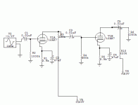
well, you need to have a B+ supply connected to the anodes...your schematic seems to show a ground connection where this would occur on the first tube, and shows no such supply on the second. For a fuzz, you could connect two diodes, one facing each direction between the grid of the second half and the decoupling capacitor off the anode. The other ends of both diodes connect to one side of a switch, the other side of the switch goes to ground.
For the exact values of resistors and B+ voltages, google "12au7 resistance coupled chart". Rp is the resistor from the anode to the B+ voltage. Ebb is the voltage connected to the top of this resistor. Rg is the resistor between the next stage's grid and ground (you only need one resistor to ground after the coupling capacitor between stages). C is the value for the coupling capacitor. Rk is the cathode resistor. Ck is the cathode bypass cap (For more distortion, try with and without a Ck at all). These are the symbols RCA uses, at least. If you can find a pdf of the RCA receiving tube manual (check on-line learning thread) it will have these tables toward the back. In my experience, using these values sounds very good, especially for instrument amplifiers. By changing the values of the resistors slightly, you can create different tones. DO NOT USE TOO SMALL A CATHODE RESISTOR!--the tube will melt.
Oh-Series filament connection is when you supply a voltage equal to adding all of the tube's heater voltages (they must draw the same current) to the first tubes heater, then run a wire to the next tube etc. Heater pin 1 connects to supply (or last tube in chain), heater pin 2 connects to the next tube in chain. Each tube "subtracts" it's heater voltage, so the chain must add up to the total voltage supply. This was mainly used in old cheap tube stuff (mostly) and should be avoided.
Parallel is when two wires are run, supplied with a 6.3v (for example) source. Heater pin 1 on all tubes are connected in a line, heater pin 2 on all tubes are connected in a line. Each line is connected to one side of a 6.3v AC supply. This works much better, but all tubes must used the same voltage heaters. \
12a*7 tubes (au, ax, etc) also have a 3rd heater pin (#9). This pin allows you to use only half the heater, but at twice the current. When wiring these tubes in parallel, wire pins 4 & 5 together (use as heater pin 1) and use pin 9 as heater pin 2. This makes it use 6.3v (more common) at 300ma, instead of 12.6 at 150ma. However, if you have a twelve volt supply, ignore pin 9 and just use pin 4 & 5 as the two heater connections.
yes, put your b+ at the end of R4...there is no equivalent resistor on section b, the resistor would be between the "top" (anode) of the tube and the capacitor. You'll need to look up how many volts and what size the cathode resistor (bottom of tube resistor) you will need. The capacitor will keep the DC high voltage from being carried to the next stage, but will allow the AC audio signal to pass.
- Status
- Not open for further replies.
- Home
- Amplifiers
- Tubes / Valves
- does some have distortion schematics for 12au7a