Hi Everybody. I'm planning to build a little valve power supply. Something to whet the appetite lets say. My first experiment with tubes. Would like to know, for a directly heated cathode rectifier does the phasing matter on the filament. I have a 5Y3 rectifier and an old transformer salvaged from a vintage radio that has a 5V winding and a 650V CT winding.
It seems to me that for an indirectly heated cathode, it wouldn't matter how you wired the filament - Some people might even run DC on the filament. But for directly heated cathode, getting the phase correct - in my mind at least - would matter. If it's in phase, the P/S output should measure 320VDC. And if it's out of phase the output will be reduced by 10V right?
Just want to get it right before wiring it and powering it.
Cheers.
@Depanatoru , thank you. That makes perfect sense. If I may inquire further - somewhat unrelated but I'm curious to better understand - you don't recommend DC filament supply at all, or you don't recommend for rectifiers. I've read DC may help eliminate hum in high gain circuits but have also read that it can result in galvanic corrosion or something over time?
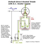
It doesn't matter, but the filament supply isn't floating, it is in series with the HT on a directly heated rectifier cathode, and even if it was floating that wouldn't be a reason why it doesn't matter.It doesn't matter as the filament supply is floating
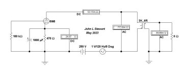
Here is something I tried about 25 yrs ago that might be interesting to others.
Reduction of power frequency ripple that could be a problem for SET amplifiers.
Something to think about,
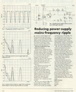
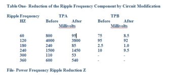
I used an HP 302A wave Analyzer to measure the ripple magnitudes. 👍
Reduction of power frequency ripple that could be a problem for SET amplifiers.
Something to think about,
I used an HP 302A wave Analyzer to measure the ripple magnitudes. 👍
Attachments

I doubt filament voltage is in series , since for direct heated active tubes this would be a huge hum source 🙂
AC current has its own path , 5V winding and fillament , it doesn't flow in the rest of the circuit , so it is a floating voltage
For the ripple reduction circuit
If the 5V winding current is not flowing in the HV circuit , not just in 10ohm + pot , the result is = 0 , and reduction is just an effect of those extra resistors in series with the HT voltage
Last edited:
This simple circuit shows how PS hum / ripple can get into the audio output of an SET amplifier. Many will point out that PS hum can be reduced further without difficulty. That is not the point I’m making, but rather to simply show there is a potential problem. And its relative magnitude. Can anyone hear this in their system? Maybe.
Many people here on DIY & elsewhere spend hours discussing the merits of this or that boutique resister or capacitor & often completely miss far larger potential problems. This particular item may be something that is completely overlooked, it doesn’t often occur. But only when the power frequency happens to be at one of the LF resonances of the speaker system.
When I had a look at this 25 yrs ago I was most interested in the filamentary type rectifiers such as 5R4 & 5U4. The tests show there is a way to reduce the magnitude of the power frequency 50/60 Hz ripple component. So why not simply wire the rectifier to take that obvious advantage.
The difference in the resistance of the HV CT winding is less obvious & to a degree swamped by the rectifier forward resistance. But many are now using SS rectifiers, the PT HV winding resistances cause a much larger effect. For my own designs I’ve often put something like 100R into each of the SS diodes lead. If one of the diodes fail shorted there is still 200R plus the PT HV winding still in series. With luck the fuse blows before further damage. If there is a fuse in the primary.
While thinking of this today I recall how the common twin triode low mu triodes used in regulated PS all recommend series resisters in their cathode circuits to help force sharing of the load currents. Tubes such as the 6AS7G/6080 are well known not to be well balanced. That may also be the case with present production of tube rectifiers such as the 5V4 & 5AR4. Has anyone looked?
In the real World where many of us spent our career years it was expected that opposing or different opinions would be backed up with some solid evidence. So far all I see is opinions. That doesn’t help much. 😀
Attachments
If you want extremely low ripple B+ for a SE amplifier , without using regulators , input inductor LC filter is the obvious solution . Then you don't worry about inbalance in transformer windings resistance and so on 🙂
You can add a small input cap 1-5 uF so the choke won't macanically buzz and for adjusting the output voltage
Even with a relativly low inductance value 2-5 H the results are very good
You can add a small input cap 1-5 uF so the choke won't macanically buzz and for adjusting the output voltage
Even with a relativly low inductance value 2-5 H the results are very good
Hi all. Thanks for the replies. @jhstewart9 that's a very interesting circuit. I guess I can say at this point I'm not too worried about noise coming from the power supply circuit I'm intending to build. At this point I'd just like to build something and make it work first. I'm leaning somewhat towards @Depanatoru's suggestion of just keeping it simple with a good old fashioned choke... That being said - I've no idea where to find a suitable choke so may need to learn how to wind something myself.
Also, on drawing out the circuit, I've also concluded the 5V winding is floating and not in series. It's obvious when drawn up. If I didn't use the 5V winding and powered with filament with a battery, it can be clearly demonstrated that the filament supply is not in series. Something that;s probably tripped me up in the past is seeing the filament windings in circuit diagrams as a secondary winding. Might be just my experience/impression but the 5V filament winding seems to be usually drawn up above the HT winding where the 6.3V filament winding is at the bottom.
One last question. Are there common HT voltages or were transformers all made to suit the radio they came from? I have one out of an old broken radio. The filament winding has a tap so you can get 5V, or 6.3V. (Or 1.3V for that matter) The HT winding seems really high for an old radio. Unloaded, looks like 415V - 0V - 415V. Not sure what it's meant to be under a bit of load. The output circuit is 2 x 6V6 in push pull. and a 6SL7 phase inverter.
One last question. Are there common HT voltages or were transformers all made to suit the radio they came from? I have one out of an old broken radio. The filament winding has a tap so you can get 5V, or 6.3V. (Or 1.3V for that matter) The HT winding seems really high for an old radio. Unloaded, looks like 415V - 0V - 415V. Not sure what it's meant to be under a bit of load. The output circuit is 2 x 6V6 in push pull. and a 6SL7 phase inverter.
It might be your mains voltage is higher than the traffo was designed for. A good test is the voltage of the heater windings. They are normally 10% high, then they are correct under the anticipated loading.
Thanks @OldHector. Definitely running the right mains supply. Trafo is from an old NZ built radio. Heater winding is multi tap and seems right 5v measures about 5.5V. The other tap measures about 6.6V (meant to be 6.3 I assume) I found an old circuit diagram for the radio but it doesn't give any voltages or trafo ratio. A hand written note suggests insertion of a 250 OHM resistor before the 1st reservoir cap to drop the voltage from 300DC to 260VDC. The input for the radio is CLC but the L is a field winding on the speaker which is missing. So I can't really easily determine what the voltage should be under load with all 5 valves operating.
Another note pointed out that the specified 5Y3 seems a bit lightweight and suggests a 5V4 would be better. I substituted the missing coil with a big resistor and powered it all up, hoping to take some measurements underload but shortly after powering it, there were little fireworks inside of thr the 6V6 output valves so I switched it back off.
Another note pointed out that the specified 5Y3 seems a bit lightweight and suggests a 5V4 would be better. I substituted the missing coil with a big resistor and powered it all up, hoping to take some measurements underload but shortly after powering it, there were little fireworks inside of thr the 6V6 output valves so I switched it back off.
So, just another thought. 415V unloaded (if that's 10% higher than it should be when loaded, might mean it's 375V secondary with a centre tap. (750V end to end) I have a feeling that's supposed to be a reasonably common secondary voltage, so maybe it's that.
If it isn't in series it isn't a directly heated cathode. And yes it is a hum source, which is cancelled by push-pull action.I doubt filament voltage is in series , since for direct heated active tubes this would be a huge hum source
Because you say so ? Most direct heated tubes were / are used in SE 🙂 , cancel that
Filament current can't flow trough the tube
Filament current can't flow trough the tube
Attachments
Last edited:
- Home
- Amplifiers
- Tubes / Valves
- Does phase matter when wiring the filament on a rectifier valve?