Jan, the circuit was used by john curl in his earlier preamps. Its my understanding that the darlington cmx will have lower noise and lower output impedance than the lm317 so it makes sense to put it downstream?
The 317 has a regulated output which is an order of magnitude lower Zout than an unregulated cmux. There may be a tiny advantage in noise, if any, but that is less important for a power supply than Zout. Zout causes signal dependent ripple which is important to avoid.
But the differences are small, so if you're happy with the setup, go for it!
Jan
Last edited:
> You should put the cap multiplier first, and the regulator 2nd.
> The way it is now a lot of the good performance of the regulator is negated by the cap multiplier.
Since it was published by me, I feel obliged to respond.
For that particular circuit, a regulator circuit using NFB and becoming inductive at HF can have stability problems, as one builder experienced.
In contrast, no such problems with the cap multiplier.
The amplifier circuit is Class A biased and has good PSRR, so a milli-ohm Zout has no real advantage.
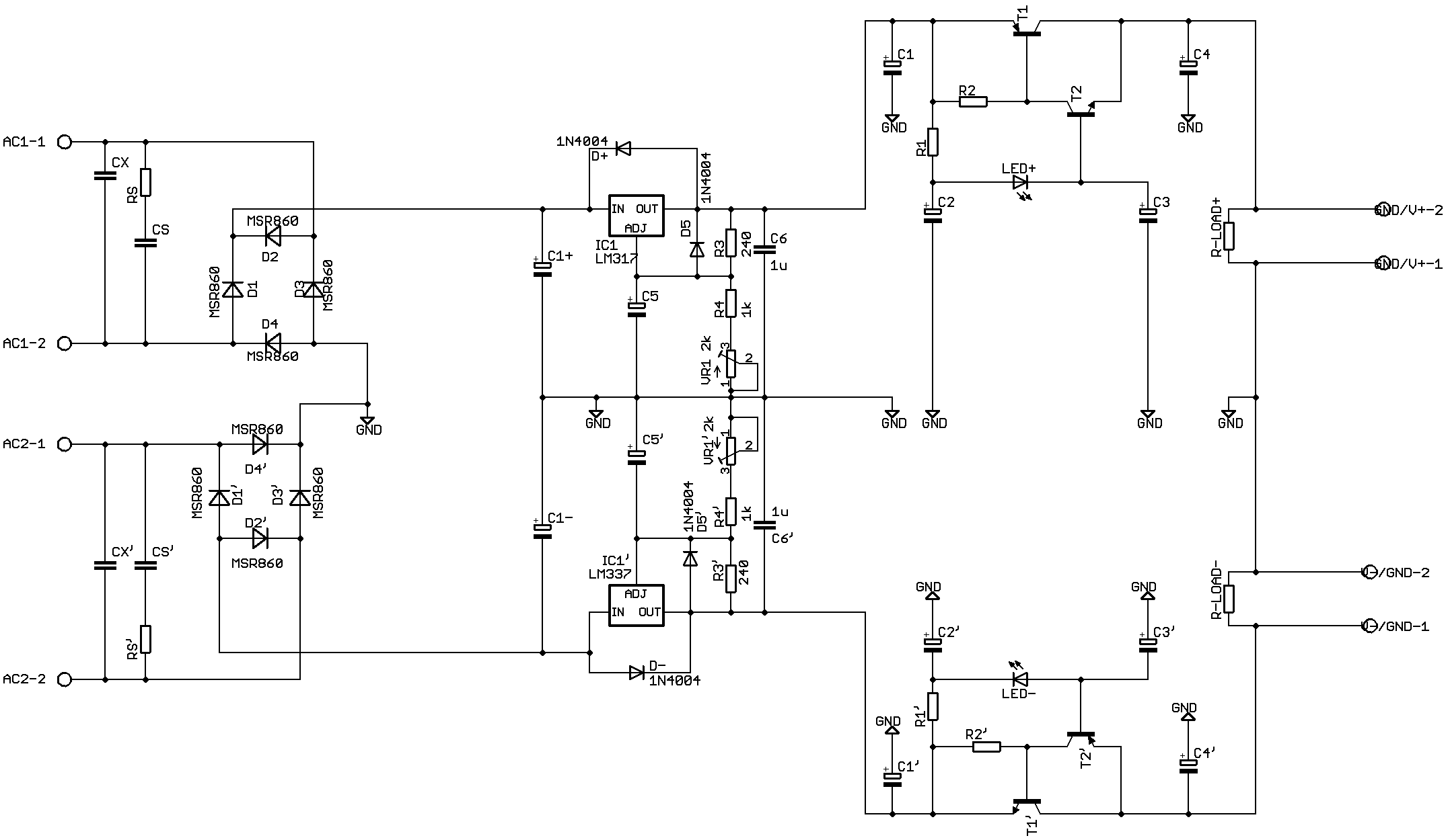
The LM317 was used here as a pre-reg to lower the ripples to very small values.
The rest would then be cleaned off by the cap multiplier.
It also has built-in protections which is quite convenient.
If one's purpose is to design a PSU as an instrument, then I agree that low Zout is important.
But in the case of the F5-HA, it is the total solution that counts.
Cheers,
Patrick
> The way it is now a lot of the good performance of the regulator is negated by the cap multiplier.
Since it was published by me, I feel obliged to respond.
For that particular circuit, a regulator circuit using NFB and becoming inductive at HF can have stability problems, as one builder experienced.
In contrast, no such problems with the cap multiplier.
The amplifier circuit is Class A biased and has good PSRR, so a milli-ohm Zout has no real advantage.
The LM317 was used here as a pre-reg to lower the ripples to very small values.
The rest would then be cleaned off by the cap multiplier.
It also has built-in protections which is quite convenient.
If one's purpose is to design a PSU as an instrument, then I agree that low Zout is important.
But in the case of the F5-HA, it is the total solution that counts.
Cheers,
Patrick
Patrick, stability is cured by a simple electrolytic cap at the output. I have no doubt that if you change the order, your supply line will be cleaner; the lower Zout gives lower signal related ripple too.
So, let us agree to disagree - there are many ways to skin these kinds of cats.
Jan
So, let us agree to disagree - there are many ways to skin these kinds of cats.
Jan
Jan, if the inherent noise of the lm317 is a limiting factor of that circuit using your arrangement of cmx>lm317, do you think the following circuit will perform even better? Using 3-pin regulators off-piste: part 4
This is actually my go-to circuit because for how easy it is to build i have found the sound comparable to a well built shunt reg. I was hoping Patrick's arrangement would better it.
This is actually my go-to circuit because for how easy it is to build i have found the sound comparable to a well built shunt reg. I was hoping Patrick's arrangement would better it.
Last edited by a moderator:
Why bother with 317's and all the extra components?
Because according to that schematic, the 317's are "biased" for 15 volts output.
A simple LM7815/7915 would do the job nicely, with a simpler (one transistor) cap multiplier before it .
I recently built a line level op amp filter using that same design, and it's rock stable, noise-free, and does the job.
The simpler design, less confusion, satisfactory performance, and reliability are my way to success.
Yes that is also a good tactic. In fact, a 317 prereg as shown is probably not only simpler and cheaper than a cmux but also better.
Someone might even try to use a 317 as a cmux - after all, it is just a super transistor with some base offset voltage of 1.25V. All the more understandable if you know that at some point, they took a 317, removed the offset voltage and called it - a super transistor. Enter the LM195/295/395. A 'transistor' with very high gain, internal current limit at 1A, thermal protection, pretty much indestructible. Only weak point is overvoltage.
Anyway, I digress. But you get the point ;-)
https://www.ti.com/lit/ds/snosbo4c/...94615&ref_url=https%3A%2F%2Fwww.google.com%2F
Jan
> stability is cured by a simple electrolytic cap at the output.
There was one 330µF (Nichicon KA, so not low ESR) close to the reg (Salas shunt), and another close to the amp.
> let us agree to disagree
Yes, with due respect.
I also use regulated supply, like your T-Reg, etc.
But only for circuits with poor PSRR and large stability margin at HF, or low bandwidth.
Cheers,
Patrick
This applies to the F5-HA, as referred to in post #16.
https://www.diyaudio.com/forums/pass-labs/271926-f5-headamp-13.html#post4831102
Patrick
https://www.diyaudio.com/forums/pass-labs/271926-f5-headamp-13.html#post4831102
Patrick
Last pass, guys. I went with this circuit (from k multiplier thread), crcrc input. I worry about the blue tracks from the adjust pins of 317/337 being too long but this is the best i could do. 60x50mm footprint so its still quite small.
 [/url][/IMG]
So for the input section of this preamp board im putting the signal trace on the bottom of the pcb and the trace length comes out to be 25cm or so. (Its a big board!) Since the trace is long and exposed i thought of shielding the bottom side with copper tape. Then an idea came to me of shielding from the top side with a ground layer drawn over the bottom trace with slightly thicker lines. Normally a ground plane would be the solution but im still going for a psuedo star ground scheme and also its a dual mono layout so a ground plane would be bit of a head scratcher.
Is it still a good idea to cover the signal trace the way i mentioned?
Is it still a good idea to cover the signal trace the way i mentioned?
Using copper tape isn't too wise, it'll potentially cause oscillation or frequency loss do to capacitative coupling.
Better to mount a board on standoffs with the chassis or shielding beneath.
It's the way its always been done and proven.
Better to mount a board on standoffs with the chassis or shielding beneath.
It's the way its always been done and proven.
Thank you. What about tracing the signal route with the ground layer like so? The red is the ground layer.

Last edited by a moderator:
Same deal, potential ground loop problems, capacitative coupling, etc.
Routing signal leads on a board requires the same procedures as using actual wiring.
Routing signal leads on a board requires the same procedures as using actual wiring.
Thats my thought too, scott. All in all im trying to mimick as closely as possible a shielded wire. The theoritical copper tape that would go on the bottom of the board would actually wrap around to the top where some of the ground trace is exposed so to form a continual layer where the tape conducts with the trace.
Last edited by a moderator:
Just using it as a shield will have very little effect unless the flow and return currents are equal. Take the diodes and CRC, the loop area can be reduced further.
It's an interesting idea, but if you are that concerned run a length of wire. 🙂
I was gonna say the same thing.😀
Just using it as a shield will have very little effect unless the flow and return currents are equal. Take the diodes and CRC, the loop area can be reduced further.
i see it, Mark. thank you 🙂
and yes a wire would work i suppose 😀
but theres also fun in trying to etch that in stone 😀
i will include a connection point next to the volume pot for the wires in case the traces react
- Home
- Design & Build
- Software Tools
- Does my layout look ok?