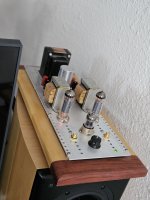
Hello! Last night I picked up this amplifier in Littlefield Arizona from its second owner. He told me that he bought it from the wife of the original owner, who had passed not long before. I thought the original owner might have been a member, so am wondering if anyone recognizes the amp? I quite like its look, and it sounds great!
Unrelated question.. the 4 ohm and 8 ohm taps aren't marked. Is there an easy way for me to figure out which is which?
Thanks!
Unrelated question.. the 4 ohm and 8 ohm taps aren't marked. Is there an easy way for me to figure out which is which?
Thanks!
Attachments
Nice Find!
Life is easy if you have a DMM - digital multimeter set to measure AC, or a VOM - Volt Ohm Multimeter set to AC; or an oscilloscope and probe.
You will also need a signal source, The Denon Audio Technical CD, slightly expensive, is the very best signal source for the $$ you can own (you do own a CD player, I hope).
A music recording, vinyl, CD, etc. do not make good signal sources, because amplitude is constantly varying.
Connect the speaker between Black and one Red tap, go to the 1kHz test tone on the Denon CD.
Start with the volume set Very low (and wear some earplugs, even low volume steady sine wave is not good for my ears, nor for yours, and medum signal level, or large signal level is not good for the speaker midrange or tweeter).
Measure the AC voltage from Black to the Red tap that has the speaker connected.
Measure the AC voltage from Black to the Other Red tap.
The one with the higher AC voltage is probably the 8 Ohm tap.
Some amplifiers have such a low damping factor that you can not be sure of the voltage differences of the loaded and unloaded tap; so reconnect the speaker to the Other Red tap, and remeasure the two AC voltages of the Red taps. If one tap always has the higher voltage in both cases, no when the the speaker loads the two different taps, the higher voltage is the 8 ohm tap.
If that still is not clearly indicating which tap is which, then . . .
Some amplifiers have global negative feedback, some will be stable without a speaker load, some will not; so use the following procedure with care:
(*) Make sure the volume is very low, and disconnect the speaker, and measure from Black, to the two unloaded Red taps;
8 is the higher voltage Red tap.
With a 1kHz sine wave, the two unloaded tap voltages will have a Voltage Ratio of approximately 7 to 10, (10 to 14).
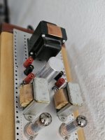
If you can read the tube types, it might help some be more sure of the identity of the circuit.
EL84, 6N1P, etc.
It is pretty easy to see that there are 2 Pentodes or 2 Beam Power tubes, and one dual triode tube.
But there are many many Diy amps and Diy clones of commercial amplifiers, so it is real hard to tell which one it is.
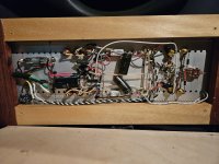
Do Not modify or change anything, until you have done both of these things:
1. Listen, Listen, Listen, Enjoy!
2. Very carefully, draw a Complete and Accurate schematic.
If there are no connections from the Red output taps to anything other than the output transformer connections; and no connections from those transformer tap to anything else in the amplifier, you do not have global negative feedback. That makes the test (*) more likely to be without any stability problem with the speaker disconnected.
Just a word of advice.
Life is easy if you have a DMM - digital multimeter set to measure AC, or a VOM - Volt Ohm Multimeter set to AC; or an oscilloscope and probe.
You will also need a signal source, The Denon Audio Technical CD, slightly expensive, is the very best signal source for the $$ you can own (you do own a CD player, I hope).
A music recording, vinyl, CD, etc. do not make good signal sources, because amplitude is constantly varying.
Connect the speaker between Black and one Red tap, go to the 1kHz test tone on the Denon CD.
Start with the volume set Very low (and wear some earplugs, even low volume steady sine wave is not good for my ears, nor for yours, and medum signal level, or large signal level is not good for the speaker midrange or tweeter).
Measure the AC voltage from Black to the Red tap that has the speaker connected.
Measure the AC voltage from Black to the Other Red tap.
The one with the higher AC voltage is probably the 8 Ohm tap.
Some amplifiers have such a low damping factor that you can not be sure of the voltage differences of the loaded and unloaded tap; so reconnect the speaker to the Other Red tap, and remeasure the two AC voltages of the Red taps. If one tap always has the higher voltage in both cases, no when the the speaker loads the two different taps, the higher voltage is the 8 ohm tap.
If that still is not clearly indicating which tap is which, then . . .
Some amplifiers have global negative feedback, some will be stable without a speaker load, some will not; so use the following procedure with care:
(*) Make sure the volume is very low, and disconnect the speaker, and measure from Black, to the two unloaded Red taps;
8 is the higher voltage Red tap.
With a 1kHz sine wave, the two unloaded tap voltages will have a Voltage Ratio of approximately 7 to 10, (10 to 14).
If you can read the tube types, it might help some be more sure of the identity of the circuit.
EL84, 6N1P, etc.
It is pretty easy to see that there are 2 Pentodes or 2 Beam Power tubes, and one dual triode tube.
But there are many many Diy amps and Diy clones of commercial amplifiers, so it is real hard to tell which one it is.
Do Not modify or change anything, until you have done both of these things:
1. Listen, Listen, Listen, Enjoy!
2. Very carefully, draw a Complete and Accurate schematic.
If there are no connections from the Red output taps to anything other than the output transformer connections; and no connections from those transformer tap to anything else in the amplifier, you do not have global negative feedback. That makes the test (*) more likely to be without any stability problem with the speaker disconnected.
Just a word of advice.
Last edited:

Thanks! And THANKS for that very detailed response. I wish that I had named the title of this thread so that others might more easily find your reply. I'll follow your advice tonight 🙂Nice Find!
This did the trick!Connect the speaker between Black and one Red tap, go to the 1kHz test tone on the Denon CD.
Start with the volume set Very low (and wear some earplugs, even low volume steady sine wave is not good for my ears, nor for yours, and medum signal level, or large signal level is not good for the speaker midrange or tweeter).
Measure the AC voltage from Black to the Red tap that has the speaker connected.
Measure the AC voltage from Black to the Other Red tap.
The one with the higher AC voltage is probably the 8 Ohm tap.
I'm quite pleased with it. Whoever's it was did a great job. Sounds great, and drives my speakers well! (MTM's with Dayton RS180's)
Hopefully someday I'll get some horns, but for now I'm very satisfied
Hopefully someday I'll get some horns, but for now I'm very satisfied
A Magnavox pull would have a more squareish chassis layout. Maybe the builder of the amp stripped all the power and output magnetics off the chassis and used his own layout scheme.
The top metal (appears to be aluminum, not steel), and the nice pattern of holes looks like a diy build.
Could be just about any simple EL84 circuit.
Could be just about any simple EL84 circuit.
+1Looks like a Magnavox pull or something similar.
the OPTs are probably of Magnavox origin
- Home
- Amplifiers
- Tubes / Valves
- Does anyone recognize this DIY amp?