Does anybody have correct AD797A spice model ?
AD provided models does not simulate correctly. Under AC analysis, displayed gain is 60dB approx where as stated value is 20V/uV (146dB). I am using LTSpice-IV for simulation.
If I am doing wrong please show me the correct way.
AC source connected to Non-Inv (+IN) input, Inv (-IN) input is grounded, Output connected to 10K load. VCC=+15V, VEE=-15V
V1 VCC 0 DC +15V
V2 VEE 0 DC -15V
VS 1 0 AC SINE(0 0 0)
XU1 1 0 VCC VEE 2 NC AD797/AD
RL 2 0 10K
.AC DEC 1000 1 1e6
.END
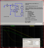
don't use .AC sim until you have the circuit working in .Tran - it is very likely your output is at a rail in the inital operating point calculation
the "simple Middlebrook" loop gain probe is much better because you can measure with the feedback loop working - but it shows "loop gain" - which is more intersting for stability
another simple way is to divide the output V by the differential input V - while the cirucit is in a working feedback amp
Ltspice is free, has gui, schematic entry and waveform plotting
.asc is the LTspice circuit file - just edit off the .txt extension
Attachments
Last edited:
Thanks 🙂
I'll try after reaching home. At work I do not use GUI (hidden practice in spare time at work). I hope you will understand.
I'll try after reaching home. At work I do not use GUI (hidden practice in spare time at work). I hope you will understand.
Hi JCX,
Your suggested technique worked flawlessly 🙂
Please clarify one doubt.
If I use OPA227 spice model with .AC command it simulates correct open loop gain (160 dB) then why we had to measure open loop gain of AD797 from closed-loop ?
Your suggested technique worked flawlessly 🙂
Please clarify one doubt.
If I use OPA227 spice model with .AC command it simulates correct open loop gain (160 dB) then why we had to measure open loop gain of AD797 from closed-loop ?
- Status
- Not open for further replies.