Various methods to do that have been used, such as acoustic damping cloths in old valve radios, motional feedback and equalization.
One way is to use a voltage amp on the woofers and the current drive to drive midTweeter (biamp) or mid + tweeter (tri-amp).
dave
I think mix mode current and voltage feedback can be useful for woofers.One way is to use a voltage amp on the woofers ...
On the speaker front, anything with real flat impedance curve (ie Elsinire Mk6) which won’t care what the output impedance or the amplifier is
Worth bearing in mind the drivers don't have a flat impedance curve and all that still implies.
The original is unknown, by definition.
Nonsense, you can take any recording as the original test signal.
(Preferably, you want a test signal that can reveal the artefacts that you want to test for.)
did you actually believe Ohm's laws can be violated? disregarded even?
The laws of physics don't apply to audio.... 😉
The point is that the relations between current and voltage, current and sound pressure and voltage and sound pressure are not entirely linear in a loudspeaker. The relation between current and sound pressure is less non-linear than the relation between voltage and sound pressure, so when you force a certain signal current through the loudspeaker and let the loudspeaker determine what the voltage will be, you get less (non-linear) distortion than when you do it the other way around.
Unfortunately you also get less damping of the fundamental resonance, so you need to find another way to deal with that. Various methods to do that have been used, such as acoustic damping cloths in old valve radios, motional feedback and equalization.
so from what i gather here, the difference is in the level of the output impedance.....
I think you are mixing up output impedance and optimal load impedance here; for a circuit designed to work under large-signal conditions, like an audio power amplifier, they are not necessarily the same. That is, your 4 ohm tap will be able to supply most power to a 4 ohm load, but the output impedance measured at the 4 ohm tap can range from well below 4 ohm for an amplifier with lots of shunt feedback at its output to many times higher than 4 ohm for an open-loop pentode output stage, or an output stage with series feedback.
Yes, I understand that's the intended case and why the series of taps are provided. Perhaps it's my mistake, but somehow I prefer using the 4 Ohm taps on 8 Ohm speakers - and give up the power transfer optimization for my perception of "it sounds better to me that way".
In looking for something to attribute that to, I've been thinking "well, it moves the impedance looking back into the amp a little lower" which may be the case, or, perhaps that's not what's happening at all. I'm open.
Rolling the amplifier part of my system into my Joilda LM1875 chip amp, again I hear something that appeals to me (bass wise) and I want to attribute that to even lower output Z than the EL84 triode strapped amp with the 4 Ohm tap can provide. Again, what I'm hearing may have nothing to do with an output Z change - but of course the engineering mind wants a rational explanation.
My interest in how tube amps sound is connected to an interest in the Qts parameter regarding enclosure design. I read (summarized) "You can get 40Hz out of this little 4" driver in this enclosure tuned somewhat lower than Fs, but the driver Qts has to be a high value". Then I read Qts is measured using a very low Z voltage source. Then I wonder what happens when you connect such a speaker/cabinet system to a tube amp - versus the one the T/S driver parameter was measured from.
Then dave shows a series of cabinet designs reflecting amplifier output Z. I think "so it matters - everyone should know this, i.e. this should be common knowledge around using tube amplification". Then the engineering mind wants to know "what successful enclosure design changes the - bass - sound least (is most tolerant) to variations in Qts as caused by connecting to different amplifier types?" I'd venture a guess that it's a sealed acoustic suspension one. Could be dead wrong about that, but I'm open to understanding all this.
Just hate to see someone go through all the trouble to construct something based around a certain driver - then connect it to their beloved tube amp and the driver/cabinet as a system doesnt work at all as it's supposed to. Or, someone putting drivers back into the closet because of insufficient Qts factor for an enclosure design they want to try, when in reality they'd do just fine with their zero feedback triode SE tube amplifier (but not something like an Adcom GFA 555). I'm certainly not knowledgeable enough (yet) to make a call like that.
Last edited:
Nonsense, you can take any recording as the original test signal.
(Preferably, you want a test signal that can reveal the artefacts that you want to test for.)
Please, let me live in the gloriousity of my statements and please don't ...(Do wathca wanna do 😴)
Worth bearing in mind the drivers don't have a flat impedance curve and all that still implies.
The drivers may not (althou with many good ones, only the bass resonance is an issue, and the lower Qm the less of an issue that is.
Xos are also often a major contributor to non-flat impedance, but that does not have to be the case (ie Elsinore Mk6) and i have seen others that aren’t too bad. I hhave seen bass resonant peaks — even fairly big ones, wiped out or largely eliminated using aperiodic enclosures.
It is not easy to do, most just assume a voltage amp and from there don’t care.
dave
Then I read Qts is measured using a very low Z voltage source.
Sometimes. Manually, I have always used the technique that turns a lowR amp into a current amp with a large R, the S+L WT2 i now use comes with its own little current amp (hiR) for measuring, and before that i had a dedicated curent amp built for testing drivers.
dave
I'd venture a guess that it's a sealed acoustic suspension one.
From all the designs i have seen, i would suspect that the leading candidtae would be a quarter-wave resonator. Look at how many different drivers work well in Frugel-Horns or TABAQ.
dave
Just a thought. Since we all, with only few exceptions to those who listen to electrostatics, connect our amplifiers to dynamic loudspeakers, which are linear motors and where motion is created by current through the voice coil and not the voltage across its terminals, then what are we actually listening to? The voltage of the amplifier or the current of the amplifier?
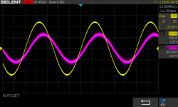
Please look at the attachment below. It is a scope screen shot.
If we can put a 2KHz sine wave through a speaker and see that the voltage produced by the amplifier on a scope (CH1 and yellow) and then create a small voltage via a current sense resistor (something low like 0.1 Ohm and hence 1/60th that of the DC resistance of a typical 8 Ohm speaker). Multiply that small voltage signal by around 60 and also put that on the other channel of the scope (CH2 and red). Now we see two sine waves, but they do not line up in time. Doing an impedance and current phase angle plot, we see that there is a +30 degrees current phase angle at 2KHz. We can see that the current sine wave is shifted to the right on the scope, relative to the voltage. We can look at that time and calculate it is exactly 30 degrees. Which sine wave are we listening to? Is it CH1 (voltage) or is it CH2 (current)? Yellow or Red sine wave?
The answer is obvious. The speaker is not reproducing two sine waves simultaneously. Hence we have to choose one or the other, we are in fact forced to choose. And the fact that we are listening to CH2, the current, then raises an interesting question:
What if the measured the distortion (put through an AP analyser or similar) on CH1 and find it has exemplary low distortion, and yet on CH2 (also put through an AP analyser or similar) it shows distortion on that sine wave, that is not on the voltage side? That would be a problem, right?
In that case, we now can see that an amplifier, when connected to a loudspeaker driver and not a purely resistive load, can have two separate distortion profiles at the same time. One on the voltage side and another on the current side. And guess which profile we are listening to? The one with distortion even if the other is maybe distortion free.
Such measurements are real. This kind of two-profile distortions are not imagined.
Amplifiers, when connected to dynamic drivers (linear motors) should be understood as current delivery systems. Here it would seem that output transformers, normally seen as step-down devices (in voltage terminology), but are in fact a step-up device (in current terms) and that tube amplifiers may well be producing more distortion on the voltage side of the amplifier, yet on the current side, a tube amplifier, as a superior current delivery service, may actually produce less distortion that the average solid state amplifier does. That is indeed a provocative thought. We may well have been measuring the wrong thing and hearing something we are not measuiring.
Attachments
Last edited:
… when connected to a loudspeaker driver and not a purely resistive load...
The loudspeaker impedance is the “R” used on the IV converter in a voltage drive system.
As usual in hifi, you have to choose your compromises. DIYers do not need to accept others compromises.
dave
so from what i gather here, the difference is in the level of the output impedance.....
Yes, that's indeed the difference between voltage and current drive.
Zout,amplifier >> Zloudspeaker is essentially current drive and results in relatively low distortion and a relatively-high-Q resonance (Qms rather than Qts).
Zout,amplifier << Zloudspeaker is essentially voltage drive and results in higher distortion and a lower-Q resonance (Qts rather than Qms).
Yes, that's indeed the difference between voltage and current drive.
It is the big difference we have to pay attention to when system matching.
dave
Utter nonsense.The answer is obvious. The speaker is not reproducing two sine waves simultaneously. Hence we have to choose one or the other, we are in fact forced to choose.
Joe has a problem understanding Ohm's law, it's well documented in the blowtorch thread
I posted numbers on this very thing on blowtorch, that showed maths that conformed 100% to Ohm's Law (as I pointed out, the impedance of a driver is not about the voltage, it is about what happens to the current of the amplifier). I reposted three times mathematical equations backed up by measurements that there is a direct correlation between current and the dB-SPL acoustic output based on Ohm's Law.
Scott Wurcer kind of finally got it and he then finally asked the right questions. The others just trolled. The two questions Scott Wurcer asked will be answered (he know what they are, that I am sure) and it will be done in a proper way.
So, I have made my statement above, it is not at all nosense and a proper peer reviewed paper with full measurements is in the works. Ohm's Law is at the centre of those measurements. These are actual distortion measurements, both electrical and acoustical, these are slated to be included.
As usual, and a trap that you have fallen into, is for some to pre-judge a subject that is actually undergoing a scientific examination - and at a later stage may regret it.
I shall not go any further here. I will, as the saying goes "keep my powder dry" - I simply wanted give people here to have something to think about and if I say anything else, the "usual suspects" will appear here and the noise floor rise so high that nobody can hear anything. C'est la vie, such is life in an age of trolling.
Cheers, Joe
Last edited:
- Status
- Not open for further replies.
- Home
- Amplifiers
- Tubes / Valves
- Do tubes actually sound like anything?