Hi all,
Newbie so please be critical.
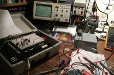
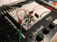
I have built a two way, 12db/octave active L-R filter on bread board and TL071/072 op amps based on Rod Elliot’s schematic.
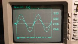
It has been surprisingly successful, I plotted the frequency response and it comes out as near as damn it where I calculated it would.
I have been reading around the topic and I Can’t work out whether the op amps need decoupling capacitors in their lower rails if they are being fed from a regulated linear supply, before I have a go at designing a PCB I would like to know if it is necessary for audio frequency filters?
With thanks,
Newbie so please be critical.
I have built a two way, 12db/octave active L-R filter on bread board and TL071/072 op amps based on Rod Elliot’s schematic.
It has been surprisingly successful, I plotted the frequency response and it comes out as near as damn it where I calculated it would.
I have been reading around the topic and I Can’t work out whether the op amps need decoupling capacitors in their lower rails if they are being fed from a regulated linear supply, before I have a go at designing a PCB I would like to know if it is necessary for audio frequency filters?
With thanks,
TL07x have internal dominant pole cap referenced to negative rail - the negative rail should be very clean and lo Z to MHz
TL07x also have a poor output stage by modern standards - if driving Cload like sheilded cable then you need a series output Z - a few hundred Ohms to be safe
the TL07x are slow enough that every chip only an inch or so apart don't need individual bypass C pairs if the power/gnd layout is good - but I'd definitely give any output driving chip its own pair
Last edited:
Thank you Jcx, power and ground layout are at the moment bread board and so I’m. It sure whether I’m any way good or not. The circuit seems stable and doesn’t oscillate, which is the main reason for these bypassing caps, if I have understood it right.
The design I have used incorporates those resistors in it’s output, thanks for the heads up though.
I understand what you have said abo the need for a clean negative rail but have to reasearch the idea of power supply impedance as I don’t know anything about it.
I have a lm7812/7912 based psu and a lm317/337 psu to play with, I have noticed that the latter seems to give a cleaner output trace from the filter.
TL072s are not super picky, IIRC Douglas Self wrote that they're generally fine with the occasional 100n cap after a few inches of trace. That's the upside of using a rather slow part that's not too happy driving less than 10-20 kOhms anyway. (4558s are much the same. You often see both with very minimal decoupling. Some rail RC filtering with maybe 100 ohms and 22 µF per rail may well do the trick for the entire circuit if you manage to keep V+ to V- inductance low, generally by routing them next to each other and close to ground.)
It's generally a good idea to include the output buffers with level trim that Rod Elliott suggests (more than the simpler unity gain buffer is not likely to be necessary). If you have tweeters sensitive enough to show actual power amp noise, some passive attenuation of the driver via a series resistor may be your best bet.
Do note that real speaker drivers often need additional EQ to get their response to a state where an ideal XO will do the job (response shaping, notching of peaks, maybe baffle step compensation). With an analog XO, time alignment between drivers generally is best done by placement.
Thank you mate, good stuff.
I posted a thread a couple of weeks ago about this topic and was similarly cautioned to measure the drivers before making a pcb, hence the breadboard approach.
I haven’t done anything like this for years and it reminds me of the 100-in-1 type electronic kits from radio shack that I had when I was a kid...
Attachments
I Can’t work out whether the op amps need decoupling capacitors in their lower rails if they are being fed from a regulated linear supply,
I would rate them as a good idea, even if not totally necessary. Small ceramics are cheap enough to not pose any penalty if you overdo it a bit.
- Status
- This old topic is closed. If you want to reopen this topic, contact a moderator using the "Report Post" button.
- Home
- Source & Line
- Analog Line Level
- Do TL071/072 op amps need power pin coupling capacitors in active filters?