Idle Current
Also -
Does anyone know what the current of the LM4780 at idle (no input or output hooked up) is.
I wanted to test it with a smaller VA rated transformer (30VCT 15VA) to make sure the rectification stage was working and so check that any offset at the output was negligible - yet I don't see any note on the Datasheet telling me whether I'm an eejit or not.
I'm not really big on super bright LEDs, I have enough of them in my lounge already. my plan was to fit one behind a nice big aluminium volume knob and have that super 'glow' effect 🙂
Re: Idle Current
In the LM4780 datasheet , the applicable term is quiescent Power and is spec'd at 110ma (typical) 170mA (max). Since people sometimes ask "is it per channel or whole chip?" I double checked the LM3886 datasheet even though I expected it to be whole chip. It agrees, LM3886 is 50/85mA and since 4780 is a pair of 3886 die, it should be double. There is 10mA difference unaccounted for but it is close enough to distinguish 1 vs 2 channels.
Whether you are a fan of superbright LED or not, I suspect for your described use you will want a superbright LED. Typical superbright vDrop is about 3.0 to 4 V depending on color, not 2V (a merely "bright" red might be closer to 2V though), and typical current for a (common) 5mm plastic encapsulated LED is 20mA for spec'd output. If that is too bright merely limit the current through the led more, but going above 20mA should be avoided for longest life and easier implementation without concern for 'sinking away heat. As with the chip datasheet, the ideal is to consult the datasheet for the LED too, or at least the closest match you can find.
raromachine said:Also -
Does anyone know what the current of the LM4780 at idle (no input or output hooked up) is.
I wanted to test it with a smaller VA rated transformer (30VCT 15VA) to make sure the rectification stage was working and so check that any offset at the output was negligible - yet I don't see any note on the Datasheet telling me whether I'm an eejit or not.
I'm not really big on super bright LEDs, I have enough of them in my lounge already. my plan was to fit one behind a nice big aluminium volume knob and have that super 'glow' effect 🙂
In the LM4780 datasheet , the applicable term is quiescent Power and is spec'd at 110ma (typical) 170mA (max). Since people sometimes ask "is it per channel or whole chip?" I double checked the LM3886 datasheet even though I expected it to be whole chip. It agrees, LM3886 is 50/85mA and since 4780 is a pair of 3886 die, it should be double. There is 10mA difference unaccounted for but it is close enough to distinguish 1 vs 2 channels.
Whether you are a fan of superbright LED or not, I suspect for your described use you will want a superbright LED. Typical superbright vDrop is about 3.0 to 4 V depending on color, not 2V (a merely "bright" red might be closer to 2V though), and typical current for a (common) 5mm plastic encapsulated LED is 20mA for spec'd output. If that is too bright merely limit the current through the led more, but going above 20mA should be avoided for longest life and easier implementation without concern for 'sinking away heat. As with the chip datasheet, the ideal is to consult the datasheet for the LED too, or at least the closest match you can find.
Variac said:Various people say that a bigger cap doesn't really help the bass, although you would think so.
A great opportunity to make one each way and compare. Then swop out the one you don't like as much.
Actually it kind of depends on the overall PS design and load as well.
I have tried both. Originally I was running the stock 10+1500 uF caps that came with the kit. The soundstage is absolutely awesome, and no complaints on the bass, which was realistic and tight (I was using 10 A transformer and bridge+parallel chips for good current delivery).
However the tone was slightly 'muddy'. Putting in large caps Peter had mentioned that it's almost like a 'Loudness' effect like in older amps, and he's kind of right. The tone becomes brighter (Cap inductance, or drop in midbass distortion?) and the bass reaches a little lower, the midrange loses a bit of its muddiness (also a bit of clarity/separation - most noticeable on vocal duets) and gets more recessed.
Imaging becomes sharper and more pinpointed, but loses on soundstage a bit, and the sweet spot shifts further back from the speakers (easy to locate speakers when sititng close). The biggest loss is in the upper midbass, male vocals get more air but less depth, and fans of bass guitars will be disappointed, as the movement is not so easy to hear, but a little more realistic.
The overall effect is IMO moving closer to reality, but away from magic. I tried all, with snubber, without snubber, etc. and finally settled on 1ohm + 0.1 uF green caps as 'snubber', 4.7 metal polyprop across the total supply, and 10000 uF Elna caps per rail. Sounds closer to commercial amps now, that may or may not be a good thing but I'm ending my experiments here.
Beware that implementing a snubber on the board is a little tough, you need to decide your config first and then go for it. You have to use both sides of the board for components, and when you do that the big caps need to go on the 'back' of the board, the resistors need to be soldered first and then the holes for the big caps are a little tough to reach unless you're using a small iron. My boards have reached the limit of the number of resolders and are looking little shabby. A spare kit will be a good idea, and they're not so expensive.
I like superbright LEDs. A piece of white acrylic in the front at a slight distance, and you can get a lovely soothing glow. Can be then piped into the front panel display hole using a short length of optic fiber...
Thanks guys, good to see I'm kinda on the right track with LEDs and to get a reality check on the current they require 🙂
Thanks ! on the current for the 4780, I'd taken the quiescent as the absolute minimum the chip required to get up and go - kinda makes sense that that's the minimum it'd require. 🙂 Alas it's very close to the current limit of the smaller trafo I have here, so no testing until the real deal arrives. 🙂
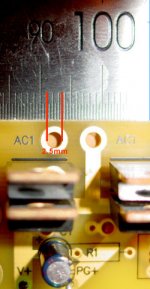
Next problem is hooking the transformer secondaries up. The PCB has 2.5mm holes (don't believe me check the pic) and I have NO idea what sort of connector is that big it would actually go in there. A loop of mains wire perhaps?
😕
Thanks ! on the current for the 4780, I'd taken the quiescent as the absolute minimum the chip required to get up and go - kinda makes sense that that's the minimum it'd require. 🙂 Alas it's very close to the current limit of the smaller trafo I have here, so no testing until the real deal arrives. 🙂
Next problem is hooking the transformer secondaries up. The PCB has 2.5mm holes (don't believe me check the pic) and I have NO idea what sort of connector is that big it would actually go in there. A loop of mains wire perhaps?
😕
Attachments
Hi,
It's to do with bass extension, efficiency, size.
Manufacturers have to choose any two from the above list and optimise for those two priorities. No manufacturer can achieve all three conflicting requirements. i.e. a speaker cannot be small, efficient and low bass extension. You must sacrifice at least one.
edit;- oops, sounds like I'm repeating what Indm said.
usually larger speakers are more efficient (sensitive). They can manage with less power rather than need more.This would mean I'd be able to keep using it if I went to larger speakers in the future, the quality of the sound might go up in some instances and
It's to do with bass extension, efficiency, size.
Manufacturers have to choose any two from the above list and optimise for those two priorities. No manufacturer can achieve all three conflicting requirements. i.e. a speaker cannot be small, efficient and low bass extension. You must sacrifice at least one.
edit;- oops, sounds like I'm repeating what Indm said.
Hi,
the smoothing caps can afford to be a lot bigger.
I am of the brute frorce brigade, according to some, but I recommend +-2mF to +-3mF per Apk per channel of output current.
50W into 8r needs 3.5Apk.
You need 4 caps for a stereo amp, each of about 7500uF to 10000uF.
If you can guarantee that on light load and maximum supply voltage your supply rails never rise above +-40Vdc then use 40Vcpas. Otherwise use 50V caps.
With amps this cheap consider using passive biamping and select the smoothing caps and other components to suit the specific drivers. You don't need to compromise.
Just to add to AndrewT's suggestion, a large capacitance can be made of a bank of smaller capacitors if you happen to have a favourite. With reduced esr/esl, some would argue this is a good way to do it.
The only problem is where to fit all of those caps on the current PCB whilst keeping short leg lengths.
Perhaps in a future build? 🙂
Trafo's & LEDs arrived today, many they're heavy (the trafos' that is).
Need to pickup some IEC sockets and fuses and then it's time to get crazy 🙂
Perhaps in a future build? 🙂
Trafo's & LEDs arrived today, many they're heavy (the trafos' that is).
Need to pickup some IEC sockets and fuses and then it's time to get crazy 🙂
raromachine said:The only problem is where to fit all of those caps on the current PCB whilst keeping short leg lengths.
Perhaps in a future build? 🙂
Trafo's & LEDs arrived today, many they're heavy (the trafos' that is).
Need to pickup some IEC sockets and fuses and then it's time to get crazy 🙂
As with many things, there is a diminishing return on capacitance. Many people feel 10,000uF is enough, if you can fit that on your board then you might try it and think about more capacitance next time. The other alternative would be to put the rectification stage, all your diodes, on a separate board and put more caps on that board, then take the rectified and smoothed DC from that board to the corrsponding spot for the diodes' output on the amp board, and put caps there too. I assume the small part of the picture you linked was an amp board, if it is only a power board then you might use a different power board altogether instead.
I would wonder if you can use some small bolts and nuts on those big holes you asked about, then use spade connectors on the wires. I'm not sure though, I have no experience with that particular board.
Hi,
7m5F 40V and 10mF 40V are not big caps. Even the 50V versions will not be large in size.
Where is the problem?
7m5F 40V and 10mF 40V are not big caps. Even the 50V versions will not be large in size.
Where is the problem?
You have to fit them on the back of the board, not the front. There is no room at the front (bottom and top respectively).
If you're using a snubber then solder the snubber in first. Be really really sure you can get to the capacitor terminals, there really is no room on those boards. I had to raise the snubber resistors by about 2 cm off the board - somewhat mitigating the purpose of snubbers - and bend them back and forth to get to the solder points of the caps on the backside...
If you pull it off you get a very compact amplifier, but they are a little difficult if you're going for big caps.
The other option is to use the main amp board for the big caps, there shold be enough room for bigger caps there.
Andrew: We're talking about the audiosector boards for 4780, those are pretty tight even for a 1mF cap on the part where the diodes are...
Caps
For what's it's worth; I have built three amps now, the third being the LM4780 as opposed to LM3875. The last was built with more caps. I used 40 1000uf Panasonic and put them into a perspex case that measured about 180 x 100mm. This made a huge difference I think.
If this is going to be a one off build and your not going to ever do another project like this again I would strongly suggest you construct a seperate power supply stage and ditch those power boards that came with the kit(no offence Peter).
My first one was built with that power board and it just doesn't compare to the second that had it's own power supply. And the same goes for comparing the second amp to the third.
...............Just My Opinion.....................😉
Attachments
Thankyou
I think the only way for me to really test the difference is to actually put an LM3875 amp into this circuit to see if the power supply really is better than my old ones. But that means pulling out the just completed LM4780.....

I think the only way for me to really test the difference is to actually put an LM3875 amp into this circuit to see if the power supply really is better than my old ones. But that means pulling out the just completed LM4780.....
Re: Caps
Hi enzedone,
I'm sure Peter won't take any offence. 😀 Anyone who's been around here as long as Peter has, has seen the endless cycle of PSU flavours for chipamps. From small caps, big caps, regulated, unregulated, batteries, SMPS, snubberised, no bypass caps, CRC filtered, capacitor multipliers - all have been "the best" PSU for GCs many, many times.
enzedone said:....I would strongly suggest you construct a seperate power supply stage and ditch those power boards that came with the kit(no offence Peter)....
Hi enzedone,
I'm sure Peter won't take any offence. 😀 Anyone who's been around here as long as Peter has, has seen the endless cycle of PSU flavours for chipamps. From small caps, big caps, regulated, unregulated, batteries, SMPS, snubberised, no bypass caps, CRC filtered, capacitor multipliers - all have been "the best" PSU for GCs many, many times.
Thanks
Greg; I am no expert, I have no test equipment. I just go on what my ears tell me, and so I have continued to make more complex(well for me anyway) power supplies, which have given me more dynamic sound. For the first amp, I was just sooooooo happy to get the thing going. But then of course, the bug bites and you just have to keep going......😉
It's so good to read other peoples experiences so you learn not what to do, or give yourself more options I guess.
And it's just one idiots(me) opinion I guess after all.
I certainly don't wish to upset anyone as I have learnt so much on this forum....
Re: Thanks
I certainly agree with you there. 😉 Audio is all about pleasing one self. I would recommend everyone do what you are doing, trying the options and coming up with their "best" combination.
When comparing amps but ear, I think you need to be able swap between the amps, or configurations, numerous times over many days (or weeks) with a good cross-section of your CDs.
enzedone said:I just go on what my ears tell me...
I certainly agree with you there. 😉 Audio is all about pleasing one self. I would recommend everyone do what you are doing, trying the options and coming up with their "best" combination.
When comparing amps but ear, I think you need to be able swap between the amps, or configurations, numerous times over many days (or weeks) with a good cross-section of your CDs.
EndZone: has your wife/partner seen the bills for all of those caps? 😛 (also thanks for the insulating pads!)
Progress!
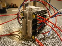
I finally found time to solder the trafo up the to board (w/ switches, fuses, iec sockets etc) and I have near to the correct voltages (29v with no load) and the led hasn't blown up 🙂
I do have on question about the chip though: I don't have an input or output hooked up at present, and I'm wondering if it should be making as much heat as it does? Very hot to touch, I'd guess about 55-65 deg C as it doesn't seem to burn. Is it likely just to be the lack of load on the PSU meaning it has to dissipate more power as heat?
Pics below:
Progress!
I finally found time to solder the trafo up the to board (w/ switches, fuses, iec sockets etc) and I have near to the correct voltages (29v with no load) and the led hasn't blown up 🙂
I do have on question about the chip though: I don't have an input or output hooked up at present, and I'm wondering if it should be making as much heat as it does? Very hot to touch, I'd guess about 55-65 deg C as it doesn't seem to burn. Is it likely just to be the lack of load on the PSU meaning it has to dissipate more power as heat?
Pics below:
Attachments

Don't worry about the heat.
I measured it and though it seems hot to the touch, it does actually not cross 55 degrees.
I would not run that amp without a load. Or any amp without a load, except for very short durations.
endezone: What power supply are we talking about? A link perhaps? If you don't mind sharing that is...
Edit: You mean you're running it without a heatsink???? 😱
😱 
I measured it and though it seems hot to the touch, it does actually not cross 55 degrees.
I would not run that amp without a load. Or any amp without a load, except for very short durations.
endezone: What power supply are we talking about? A link perhaps? If you don't mind sharing that is...
Edit: You mean you're running it without a heatsink????
😱 - Status
- Not open for further replies.
- Home
- Amplifiers
- Chip Amps
- Do I really need/want a Gainclone?