So I purchased Linear Systems LSJ74/LSK170 JFET from the store "Grade A". Do I really need them matched if there Grade A.
Thanks for Answers... JP
Thanks for Answers... JP
The grade means a Idss range. E.g., 2 to7mA is grade A, 8 to 15mA is grade B, etc.
That's not exact...
If you are building a F5, you will need N-Ch and P-Ch jfets at 8-10mA idss, I think.
if you bought the bulk jfets, chances are you will not find a matched pair.
They are remnants of the matched jfets.
Either wait for the store to supply matched pairs or find a reputable vendor.
That's not exact...
If you are building a F5, you will need N-Ch and P-Ch jfets at 8-10mA idss, I think.
if you bought the bulk jfets, chances are you will not find a matched pair.
They are remnants of the matched jfets.
Either wait for the store to supply matched pairs or find a reputable vendor.
well ......
(and B grade would be better ....... OK , everything under 5mA is wimpy in my book , so shoot for more and keep them at least in 20% bracket , regarding Idss ; you can use 9V battery instead of 12V supply ; your DMM is good for mA-meter)
(and B grade would be better ....... OK , everything under 5mA is wimpy in my book , so shoot for more and keep them at least in 20% bracket , regarding Idss ; you can use 9V battery instead of 12V supply ; your DMM is good for mA-meter)
Attachments
Last edited:
Papa sent me this...
LS A grade will work, but best to check the Idss figures on them, as you want
them within about 1 mA of each other. There is a good chance they are close
enough already, but you would want to check that.
If you have a multimeter and a battery/supply you can check Idss pretty easily.
Tie the Gate and Source together and measure the current with something like
+10 V applied to the Drain for K170, and –10V for J74.

This ?
are you able to decipher little schematic I posted up?
Sorry Z.. I am unable to understand all ... in the pic.. Im just wondering if I do the pic I posted if it would work
Ok Zen,
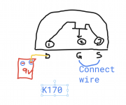
I read your image and I see this.
N Ch
+ 9 volt battery to + multimeter
- multimeter to drain
Gate to S to - side of 9volt battery.
Yes?
I read your image and I see this.
N Ch
+ 9 volt battery to + multimeter
- multimeter to drain
Gate to S to - side of 9volt battery.
Yes?
for SK170:
by datasheet , locate Gate and Source pins , connect (soldering is simplest , if not fastest ) them together and connect to negative of 9V battery
Drain connect to black DMM probe , set DMM for 20mA (or similar range) DC , connect red DMM probe to battery positive and read on screen ....... wait numbers to settle (15-20sec probably) read , remember and disconnect probes
write down on paper measured mA number , desolder tiny bugger and place near written number
repeat for each SK170 you have
for SJ74:
by datasheet , locate Gate and Source pins (same pinout as for SK170), connect (soldering is simplest , if not fastest ) them together and connect to positive of 9V battery
Drain connect to red DMM probe , set DMM for 20mA (or similar range) DC , connect black DMM probe to battery negative and read on screen ....... wait numbers to settle (15-20sec probably) read , remember and disconnect probes
write down on paper measured mA number , desolder tiny bugger and place near written number
repeat for each SJ74 you have
@jonparkhurst, you want the multimeter set to read current 20 or 200mA setting.
The positive of the power supply or battery goes to the positive lead on the multimeter, then the negative lead of multimeter to the drain "D" of the jfet.
Negative lead of the power supply goes to the gate and source pins of jfet.
The positive of the power supply or battery goes to the positive lead on the multimeter, then the negative lead of multimeter to the drain "D" of the jfet.
Negative lead of the power supply goes to the gate and source pins of jfet.
for SK170:
by datasheet , locate Gate and Source pins , connect (soldering is simplest , if not fastest ) them together and connect to negative of 9V battery
Drain connect to black DMM probe , set DMM for 20mA (or similar range) DC , connect red DMM probe to battery positive and read on screen ....... wait numbers to settle (15-20sec probably) read , remember and disconnect probes
write down on paper measured mA number , desolder tiny bugger and place near written number
repeat for each SK170 you have
for SJ74:
by datasheet , locate Gate and Source pins (same pinout as for SK170), connect (soldering is simplest , if not fastest ) them together and connect to positive of 9V battery
Drain connect to red DMM probe , set DMM for 20mA (or similar range) DC , connect black DMM probe to battery negative and read on screen ....... wait numbers to settle (15-20sec probably) read , remember and disconnect probes
write down on paper measured mA number , desolder tiny bugger and place near written number
repeat for each SJ74 you have
I can do this.. instead of solder.. can I just clip together ? or must solder for best results.
Thanks All.
few thoughts ...... I'm really not comfortable - thinking that you're not confident enough to conduct so simple measurement by your own ......... how you think to finish entire amp , without making BigBadaBoom and , quite possibly , being zapped with mains voltage ?
don't get me wrong ...... for instance , I know that I could never be able to be medical worker and car body repairer .... I know my limits ........
don't get me wrong ...... for instance , I know that I could never be able to be medical worker and car body repairer .... I know my limits ........
I can do this.. instead of solder.. can I just clip together ? or must solder for best results.
Thanks All.
yes of course , tiny clips and you're good
Zen,
Fair statement. I have built two sets of ACA's 1.1 and 1.6 with perfect results, couple pre s and so forth. You're right. Boom makes me think, but I m going to try, there are great schematics and build guides as well. Slow and steady, will make two great amps. If not, I may not need my dfib machine anymore.. I appreciate the help and caution. I will report back..
Fair statement. I have built two sets of ACA's 1.1 and 1.6 with perfect results, couple pre s and so forth. You're right. Boom makes me think, but I m going to try, there are great schematics and build guides as well. Slow and steady, will make two great amps. If not, I may not need my dfib machine anymore.. I appreciate the help and caution. I will report back..
- Status
- Not open for further replies.
- Home
- Amplifiers
- Pass Labs
- Do I really need matched pairs