I am upgrading the filter caps on the linear power supply of an old tube pre-amp, and I was wondering how important it was to use small value shunt capacitors in parallel with the electrolytics if my replacements are already low esr (in the 100s of milliohms for caps in the 10s to 100s of microfarads)?
It depends on the capacitors frequency response. Take a look i the data sheet for 100 kHz. Modern eletrolytics are far better than old, but I do not know if it is so for HV caps as well. And polypropylene is better due to lower losses, if you care of all details.
Tube devices operate at a much higher impedance than solid state, so there's much less of a need to bypass electrolytics. Then again, extra caps are cheap enough for one-off DIY designs, so it can't hurt.
Wherever low inductance rails are required - specially with class d-amps - these low inductance caps are located as close as possible to the sensitive part of the circuitry.
A shunting cap placed directly at the bulk caps is without effect simply because the wiring inductance is in between.
Certainly these do no harm.😉
A shunting cap placed directly at the bulk caps is without effect simply because the wiring inductance is in between.
Certainly these do no harm.😉
Just close your eyes and pop a cap on?
The great thing about electronics is you can DESIGN with confidence.
Who here thinks about resonances? Every part has R L and C. Every part has at least one resonance. Any two parts together will have *multiple* resonances.
There was a time when electrolytic caps had large ESR and also large inductance. Back in 1959. Today the inductance is similar to a piece of wire between the cap terminals.
Say you put 0.1uFd across 40uFd. The 40u cap Z drops from 4r @ 1kHz toward 0.7r @ 10kHz. It may typically have 2uH of inductance which drives Z higher.
With a 0.1uFd across that, we have a parallel tuned circuit a lot like the input to an AM radio. (Who here built crystal radios?) Like the radio the impedance goes HIGH at some point. For the estimated values here, around 330kHz. And 40 Ohms, far worse than the 40uFd alone.
This don't help. Does it hurt? Most tube audio amps have little gain at 330kHz. Not just the nominal gain between jacks, but any internal gain may make trouble.
If you "need" to do this, you may actually want "high ESR" which would spoil the Q of the resonance, lower and flatten the 330kHz resonant tuned circuit.
Attachments
Oh yes... Combinations with electrolytics and ceramics should be avoided of resonance reasons. But if you add 10u/400V to the big (100u or so) low ESR electrolytic? The resonance frequency will be lowered and may interfere with the signal. Many years ago I constructed a signal filter for telephone lines (to damp frequencies from 4kHz to some MHz) and struggled with a lot of resonances which needed to be damped out with resistors. Yeck. So, OK, I'll take back the most of what I wrote before and calim the opposite.
Some real, measured data can be found here:
paralleling film caps with electrolytic caps
Draw your own conclusions....
paralleling film caps with electrolytic caps
Draw your own conclusions....
I value your real measurements with different cap combinations. My conclusion is that these impedance curves are irrelevant to real audio amps as they where probed directly at the bulk caps terminal - certainly the best way to do it. But at the point where this matters you will find the local caps that dominate impedance no matter of any far distant shunt caps. Otherwise this was a poor design by itself.
Local bypass is OK, but many people simply add a 100nF cap directly across the E-caps (and I think it is the subject of this thread)
Local bypassing versus simply adding a 100nF cap at the E-cap, is worth a detailed consideration.
Depending of how close these caps are, how the routing is done, one could fear ringing.
Is it safe to say, no problem ? because there will always be, enough inductance to separate them.
Depending of how close these caps are, how the routing is done, one could fear ringing.
Is it safe to say, no problem ? because there will always be, enough inductance to separate them.
The most ridiculous board layout I have ever seen:
On a digital board, all IC bypass caps parked together at a corner of the board, layed out exactly as drawn on the schematic.
Later we had an update with all these paralleled caps replaced by a single one, so large the board could not slide inside the rack.
On a digital board, all IC bypass caps parked together at a corner of the board, layed out exactly as drawn on the schematic.
Later we had an update with all these paralleled caps replaced by a single one, so large the board could not slide inside the rack.
When the C/c ratio is <100, paralleling rarely causes problematic resonance issues; that is one of the conclusion of the studyDepending of how close these caps are, how the routing is done, one could fear ringing.
Is it safe to say, no problem ? because there will always be, enough inductance to separate them.
Who here thinks about resonances?
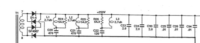
ARC have had a solution for this for the last 30 years. Interestingly, they use the same decoupling components in all their power supplies, whether B+ or heaters. Very easy to replicate.
US5036292A - Decoupled electrolytic capacitor
- Google Patents
Attachments
*double facepalm*The most ridiculous board layout I have ever seen:
On a digital board, all IC bypass caps parked together at a corner of the board, layed out exactly as drawn on the schematic.
Later we had an update with all these paralleled caps replaced by a single one, so large the board could not slide inside the rack.
This exactly proves that there still are many out there who don't know what they're doing.
Best regards!
Best regards!
Basically NO. A common DIY mod based on assumptions, not science.
Save your small films for over right at the load as bypass caps.
A better design is using multiple smaller main caps for even lower ESR.
Funny, people even comment on leakage for PS caps, yet good design will have a bleeder across it anyway!
And of course, if your equipment is more than 10 or so years old, the very best mod is to just re-cap it in the first place. Just swapped the mains in a Parasound Z3. P/S noise dropped by 24 dB. New beats old with magic tweaks every time.
PS:
A patent does not say if it works or not, just that it is an idea. Unique idea or unique application. The only invention you can't patent is preputial motion.
Application I would assume as expired as to previous art. This idea goes back to the 50's.
A patent does not say if it works or not, just that it is an idea. Unique idea or unique application. The only invention you can't patent is preputial motion.
Application I would assume as expired as to previous art. This idea goes back to the 50's.
- Home
- Amplifiers
- Power Supplies
- Do I need shunt capacitors when using low ESR electrolytics?