OK, I had an idea, but I started thinking and I don't think it'll work anymore. I think I might be creating some kind of feedback loop but I could use an expert opinion.
I drew it out in paint, lol, so bare with me...
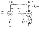
Notice there is NO resistor between the plates.
What is the general value required? Or typical voltage drop required between plates?
Or will it work...
I drew it out in paint, lol, so bare with me...
Notice there is NO resistor between the plates.
What is the general value required? Or typical voltage drop required between plates?
Or will it work...
Attachments
Grounded??? I don't see how, it'll be decoupled and plates aren't grounded, cathodes are. I think you're confusing me.
Could you elaborate please?
Could you elaborate please?
Grounded??? I don't see how, it'll be decoupled and plates aren't grounded, cathodes are. I think you're confusing me.
Could you elaborate please?
In that schemo, both plates are at AC ground, since the DC rail is AC ground. An ideal DC source won't have any voltage variations across it. If there is no AC across the DC rail, then that's AC ground.
Active devices (hollow state or solid state) won't develop any output without either a passive or active load, and here there is none.
So, I'll need the resistor between the DC rail and 6s4 plate to allow for an AC to pass to the grid on the 300b, I thought as much, never seen a circuit like what I drew.
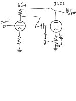
So then what sort of value is needed? If I threw a 5k in there would that be OK? I think I measured approx. 25V drop on 5kohm. Or does it need to be more to be equivalent to voltage swing needed or something? ie; approx. 150V drop???
So then what sort of value is needed? If I threw a 5k in there would that be OK? I think I measured approx. 25V drop on 5kohm. Or does it need to be more to be equivalent to voltage swing needed or something? ie; approx. 150V drop???
Lol, I'm not, I just try stuff out, learning, occasionally with success and sometimes with disaster, if I don't know I ask. I really prefer to learn that way as it's way more exciting. I've been playing around with the same amp nearly everyday for hours tweaking for over a year, it's allot of fun for me. However I think I'm developing Audio Autism.what amp are you trying to build? your circuit as shown will not do anything...
oh btw the 300b is a Driver tube, a cathode follower for an large triode, so it's plate is good on B+
Trial-and-error valve amp construction without the benefit of any electronics knowledge seems a bit of a Darwinian pastime.
no wokie.
yes the B+ as well as the DC ground is AC ground.
I think it was covered in 2nd semester, a couple of decades ago.
as well as common amplifier topology.
yes the B+ as well as the DC ground is AC ground.
I think it was covered in 2nd semester, a couple of decades ago.
as well as common amplifier topology.
Agreed. This seems like it'll be a lesson in frustration for the OP.Trial-and-error valve amp construction without the benefit of any electronics knowledge seems a bit of a Darwinian pastime.
OK, If I did this, this would work, and both plates are still being fed by B+ like I already mentioned (by me) the difference is a resistor, and still no one can suggest a value???
BTW...
I didn't know a degree in amp topology was required to post on a forum.
I didn't study amp topology in school a decade ago, but I am still studying Geophysics...(4th year 🙂) I'm try to catch up to your brilliant and creative minds. I mean I could probably design a program in matlab to answer my question, but sometimes it's nice and easier just to ask some nice friendly people why.
Also I'm smart enough to know that if I did implement that circuit nothing bad would have happened and as I suspected... no sound, however my understanding for no sound may have been premature. Thanks for the education, I never thought of B+ that way.
Darwin eh? I've been playing with electricity since I was a kid (Dad's an electrician and there was always wire, switches, and sockets around, not to mention power tools and gasoline...), I don't know topology, but I have an intuition and can repair nearly anything (that's the easy part). Never looked at a schematic until a year ago, been playing with 1kV B+ nearly everyday a little longer than that. Oh and the best part is not only am I still alive, but I have offspring...
Attachments
Google "tube load line" to discover how anode resistor values are chosen.
Remember, intuition has to be constrained and educated by facts - if not it can lead you seriously astray.
Playing with 1kV supplies without the benefit of a good knowledge of schematics is a good way to enter for a Darwin award. Since you have kids, does your wife have you well insured?
Remember, intuition has to be constrained and educated by facts - if not it can lead you seriously astray.
Playing with 1kV supplies without the benefit of a good knowledge of schematics is a good way to enter for a Darwin award. Since you have kids, does your wife have you well insured?
HaHa first hit on google reveals:
How to "Screw Around" Your Tube Load Line
a. k. a.
A Day in the Life of the BOGUS "Circuit Designer"
This sounds like the perfect page for me!
How to "Screw Around" Your Tube Load Line
a. k. a.
A Day in the Life of the BOGUS "Circuit Designer"
This sounds like the perfect page for me!
I don't come here to post good ideas, I come here to ask the dumb questions.
The only dumb question is the unasked one.
Go here: Steve's Tube Pages. Scroll down to "Loadlines Pt 1" (in the rightmost column). That'll answer all the "dumb" questions.
- Status
- Not open for further replies.
- Home
- Amplifiers
- Tubes / Valves
- Do I need a resistor between plates? pic included.