Long story short.
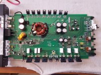
DLS XM10 class AB mono.
Amp came in for repair. Goes right away in protect. Pin 10 on the SG3525 is at 5v. Grounded it. Power supply section works fine. OP amps voltages are fine at 14.8v. Rail voltages are present.
But the amp produces approximately almost full negative rail voltage at the + speaker output. If not grounding pin 10 of the SG3525 protection circuit kicks in.
I've pulled out all of output transistors and their drivers - all read fine over ~140 Hfe.
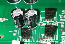
Q60, Q61, Q62 - reads over ~250Hfe, but the board has some marks from overheating on the bottom side. I see there are heatsinks location on the board, but the heatsinks are missing (oh cheap China) 😀
Q17, Q18, Q53 - have been changed with brand new ones
R167 - was out of tolerance - changed this one too.
I've checked each one of the transistors and there is no short anywhere. I can't find what causes the amp to DC offset so badly. Checked almost every resistor, diode and transistor and they all read accordingly.
Schematics are here:
http://www.tehnari.ru/attachments/f114/450443d1579809818-noaia-xm10.pdf
Last page is the exact one.
DLS XM10 class AB mono.
Amp came in for repair. Goes right away in protect. Pin 10 on the SG3525 is at 5v. Grounded it. Power supply section works fine. OP amps voltages are fine at 14.8v. Rail voltages are present.
But the amp produces approximately almost full negative rail voltage at the + speaker output. If not grounding pin 10 of the SG3525 protection circuit kicks in.
I've pulled out all of output transistors and their drivers - all read fine over ~140 Hfe.
Q60, Q61, Q62 - reads over ~250Hfe, but the board has some marks from overheating on the bottom side. I see there are heatsinks location on the board, but the heatsinks are missing (oh cheap China) 😀
Q17, Q18, Q53 - have been changed with brand new ones
R167 - was out of tolerance - changed this one too.
I've checked each one of the transistors and there is no short anywhere. I can't find what causes the amp to DC offset so badly. Checked almost every resistor, diode and transistor and they all read accordingly.
Schematics are here:
http://www.tehnari.ru/attachments/f114/450443d1579809818-noaia-xm10.pdf
Last page is the exact one.
Attachments
Last edited:
With the black probe on the negative speaker terminal for all measurements, unless noted.
DC voltage on?
Primary ground?
Base of Q17?
Base of Q18?
You stated that the op-amp voltage was correct at 14.8v. Did you mean both positive AND negative 14.8v?
DC voltage on?
Primary ground?
Base of Q17?
Base of Q18?
You stated that the op-amp voltage was correct at 14.8v. Did you mean both positive AND negative 14.8v?
This being with the amp in protect without grounding pin 10 at the SG3525
DC Voltage - after turning the amp, voltage jumps to minus 20v and then slowly drops
Primary ground - 0v
Base of Q17 - 0v
Base of Q18 - after turning the amp, voltage jumps to minus 7v and then slowly drops
This being with the amp WITH grounding pin 10 at the SG3525
DC Voltage - after turning the amp, voltage jumps to plus 45v then bounce to -20v and then drops to 0v. Turning off the amp leaves -20v between the output terminals which very slowly drops to 0v.
Primary ground - 0v
Base of Q17 - minus 0.01v (could it be my DMM ?)
Base of Q18 - minus 0.04v (could it be my DMM ?)
After 1 minute of idle and current draw of only 0.5A, Q60, Q61, Q62 got extremely hot to the point, i wasn't able to touch them.
You stated that the op-amp voltage was correct at 14.8v. Did you mean both positive AND negative 14.8v - YES SIR, that's correct, when pin 10 of the SG is grounded yes, if not, amp goes in protect very fast.
If you're questioning what your meter is reading, use a different meter or confirm that this meter is working correctly.
Is R164 within tolerance?
What is the DC voltage on each terminal of that resistor (black on secondary ground)?
What is the DC voltage on each terminal of that resistor (black on secondary ground)?

No. Changed C7 anyways. No difference. Still the same. Voltage jumps to minus 6 volts and drops slowly.
I thought that you had already replaced them.
Is it possible that the board has become conductive where it got hot?
Is it possible that the board has become conductive where it got hot?
I've replaced them already 2 times. Hfe reads ~250. I've just fitted new ones - same issue.
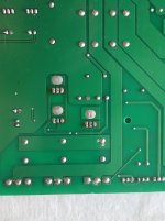
"Is it possible that the board has become conductive where it got hot?" - this is what i was thinking for the last 2 days...but it doesn't look like that, at least from outside. Picture attached
"Is it possible that the board has become conductive where it got hot?" - this is what i was thinking for the last 2 days...but it doesn't look like that, at least from outside. Picture attached
Attachments
I think the board is conductive. I don't see any other way for Q61/62 to be driven on any other way.
It's also odd that the amp isn't trying to correct for the DC offset. As soon as there is a tiny bot of offset, the differential amplifier should see the offset and drive all it possibly can to correct. Is there a break between R164 and Q18's base?
It's also odd that the amp isn't trying to correct for the DC offset. As soon as there is a tiny bot of offset, the differential amplifier should see the offset and drive all it possibly can to correct. Is there a break between R164 and Q18's base?
Last edited:
"Is there a break between R164 and Q18's base?" - no, direct short.
Is there a way I could test to be sure enough it's the board itself the problem ? I've checked some other forums and google about this amp and there were couple of russian ones that had the same issue - and the issue was actually conductivity in the board exactly at the same place - around Q61/Q62.
One of the users actually saved the amp by cutting a hole from the board around those transistors and jump wiring the BJTs. 😱
On the posts 3 and 7, the voltage on the base of Q18 seem to conflict.
If you scrape between the pads of Q61 and Q62, does the fiberglass look like it's darker than it is in other locations?
Have you touched/rubbed your scope probe (DC coupling) around on the top and bottom of the board around those transistors, with the amp on to see if the trace ever moved from the reference point?
- Home
- General Interest
- Car Audio
- DLS XM10 mono class AB issues