After mounting several amplifiers I discovered that I like amplifiers with high impedance output with my boxes.
I always thought it was the H2 of the tubes and the SE that appealed to me, but discovered with a transconductance amplifier that was the impedance that made the magic.
This is my story.
Regards
Thiago
I always thought it was the H2 of the tubes and the SE that appealed to me, but discovered with a transconductance amplifier that was the impedance that made the magic.
This is my story.
Regards
Thiago
Hugh has a point here about efficiency though. It's pretty much like most of my SE Class A amps - burns heat like nobody's business and doesn't put out too many watts. Sounds wonderful though so - really an ideal headphone amp.
Kean, you just doubled the complexity! 😱
Well, it might be worth it. Who knows?
Certainly worth it if you want more output. It's only 1 more transistor and 2 LEDs.
Last edited:
For Keantoken's schemtic: I only see one extra active over the OPs schematic with compensation added.

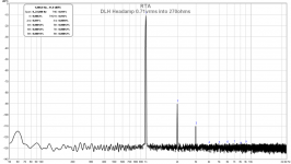
Here is my DLH headphone amp performance, driving 0.71vrms into 270ohms:

Still a nice performer.
Here is my DLH headphone amp performance, driving 0.71vrms into 270ohms:
Still a nice performer.
Attachments
Last edited:
It's difficult to argue that H2 at -80dB, H3 -100d, and H4 and beyond below -115dB is not a good result.
It SHOULD sound very good.
But then, we have to consider the noise, big issue with cans, and slam for bass. Last, how are the spatial qualities; can you locate all the instruments left to right front to back in the orchestra, and does the solo instrument soar over the riffraff behind it?
Nice measurements, X. You are the king of numbers - any amp would quake in its solder pads when you approach with your probes......
Hugh
Thanks Hugh. It sounds quite nice, spatialization and soundstage. I need to work on adjusting those source resistors to give it more slam. It is a bit reserved and polite at this point but I think the issues are all fixable with some tweaking. Certainly there is a lot of promise here for such a compact headphone amp.
Hugh & company
I think that many forget a fundamental factor, the increase of noise and of continuous in the electrical network. I commented as a great sufferer of this problem, regardless of the amplifier used. I have managed to alleviate much but I still notice the sound improvement after 8:00 pm and in the weekend, in my home (Tarragona, Spain).
I think that many forget a fundamental factor, the increase of noise and of continuous in the electrical network. I commented as a great sufferer of this problem, regardless of the amplifier used. I have managed to alleviate much but I still notice the sound improvement after 8:00 pm and in the weekend, in my home (Tarragona, Spain).
Interesting observation you make of electrical and ambient or background noise. It makes a significant difference if it is quiet around you. I recall years ago, living on a farm, especially at night, you can truly appreciate listening to your music since the nearest man-made noise is about 10 km away.
I still notice the sound improvement after 8:00 pm and in the weekend, in my home (Tarragona, Spain).
Me too
Many thanks to Djago and all the other contributors to this nice (in terms of complexity vs. yield) little amp! I've been caught and I'm thinking of a build of my own.
Presently a German Surplus vendor happens to sell 24 V 5 A laptop bricks, which basically could be modified for to act as the PSU here (there's a Connection from safety earth to the negative output terminal which would have to be removed). Though they are rather cheap at about 6 EUR/ea., they arent of cheap construction, even offering active PFC.
Which way would I have to modify this amplifier design to make it capable of ±24 V supply rails? Would it need bigger or more power transistors?
Best regards!
Last edited:
Many thanks to Djago and all the other contributors to this nice (in terms of complexity vs. yield) little amp! I've been caught and I'm thinking of a build of my own. <snip>
At these amp you can not increase the rail voltage that much.🙂 Also these is a Class A amp that mean it need (require)a serious power supply. The absolute worst think you can do if you mess up (under size) the power supply. At Class A we usually use oversize transformer with a lot of capacitors (uF). CRC or CLC set up. These project deserve much better for start that you mentioned.
Greetings
I have had great success using SMPS bricks for Class A. Use a DC-to-DC converter followed by a simple mosfet cap multiplier to clean up noise and provide soft start. Bricks rated for 4.6amps 19v were used in my SE Class A amp to power both channels at 1.2amps each. You will get much lower mains noise with SMPS. But it requires the cap Mx to slowly ramp up otherwise SMPS senses in rush as a short and shuts down.
I use this:
DROK DC Car Power Supply Voltage Regulator Buck Converter 8A/100W 12A Max DC 5-40V to 1.2-36V Step Down Volt Convert Module Amazon.com: DROK DC Car Power Supply Voltage Regulator Buck Converter 8A/100W 12A Max DC 5-40V to 1.2-36V Step Down Volt Convert Module: Industrial & Scientific
And cap Mx is this:
Juma's Easy-Peasy Capacitance Multiplier
he probably just meant to say something like "those that know that they prefer amps with less harmonic distortion will likely prefer the DLH to this other commercial offering i just measured"
😀
mlloyd1
😀
mlloyd1
I don't believe I can tell from the charts which amp will sound bettr to me (on my speakers at least).
Hugh & company
I think that many forget a fundamental factor, the increase of noise and of continuous in the electrical network. I commented as a great sufferer of this problem, regardless of the amplifier used. I have managed to alleviate much but I still notice the sound improvement after 8:00 pm and in the weekend, in my home (Tarragona, Spain).
I believe if you use a SMPS and DC-DC step up converter followed by a Cap multiplier then a CRCRC filter bank like I do, all external line noise (from others etc) are effectively filtered out. The use of multiple levels of RLC filters in the SMPS and the DC-DC step up converter provides two stages of intense LC filtering that removes most of the junk in the mains. A lot like RLC EMI filter IEC sockets but with steeper slopes.
Maybe you are right but... how many DIY/commercial amps use that type of power (good SMPS with low noise like expensive Hypex and others) and filtering?
That is why I was interested in the DIY First One amp (with MOSFET and expensive SMPS) whose creator has been missing for months.
That is why I was interested in the DIY First One amp (with MOSFET and expensive SMPS) whose creator has been missing for months.
Except it doesn't have to be expensive. For example, $15 HP OEM 19v 4.65amp SMPS, $10 DC step up converter, $5 cap Mx. The SMPS does have to be higher quality and not $7 garbage from no name brands.
Hi Guy's,
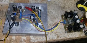
for those who are interested I have also now completed a prototype of the DLH. Yes it is extremely simple. Has only a few components, was made relatively small and performs okay.
Unfortunately it is very unstable. The off-set runs all over the place and the amp will need some work using an auto off-set adjust if it was to be used in your installation.
Because I am also a fanatic head-fier I used it last night after completion as a head phone amp. It was a little ridiculous running it at 1.3 Amp bias driving a pair of HD 800s, but I tried it because XRK's suggesting this and also to satisfy my own curiosity.
I was met with serious listeners fatigue after an hour or so, and felt very tired of music, although I can listen to my two-transistor SE for days without removing my phones. In fact I feel undressed without them.
I must admit, the amp does not sound bad at first listen, maybe even impressive but as time goes on it just didn't do it for me. It may be perfectly suitable for another's taste. I listen to mostly Jazz, popular classics, 60's 70's and a little early eighties rock and blues.
If someone would like my PCB plots, e-mail me and I will forward it to you. I don't want this thread to become cluttered with everyone's PCB layouts.
Attachments
Hi Nico,
Nice build! I never listened to the full size DLH as headphone amp for too long - mostly for debugging noise and hum and then maybe tracks. I was too fearful of the possible massive DC rail flop that would kill my cans.
I wonder if you may be experiencing some oscillations (inaudible) but they cause fatigue? This amp is very high bandwidth and needs RF filter on input, and RF filter on output to prevent RF pick up from cans coming back to the amp. Did you look at FFT or oscope output?
I notice you only have 4 actives and 2 BJT's - if you build the version with the 4 BJT's the drift would be a lot less. Otherwise, you can cap couple the output and not worry about DC drift with two.
- Home
- Amplifiers
- Solid State
- DLH Amplifier: The trilogy with PLH and JLH amps