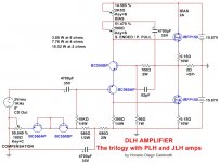
This very simple design has all the ingredients to satisfy even the most demanding DIYers. The output power in pure class A operation is 15.52 W at 2 ohms and 1 KHz, or 7.76 W at 4 ohms and 1 KHz, or 3.88 W at 8 ohms and 1 KHz. THD is only 0.025 % at 15.52 W and 1 KHz (2 ohms). THD is only 0.0024 % at 7.76 W and 1 KHz (4 ohms). THD is only 0.00091 % at 3.88 W and 1 KHz (8 ohms). Voltage gain = 8,9 dB.
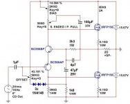
Only two stages. Four transistors. Very few components. Its performance is surprisingly good, despite its total simplicity.
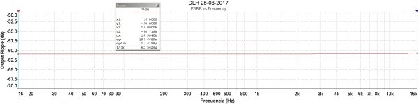
High bandwidth. Ultra low distortion. Input in single ended configuration. Output in single ended or push pull configuration, entirely adjustable by the position of a trimpot. PSRR: 61 dB across the entire audio bandwidth.
I want to hear comments from those who intend to build this simple amplifier.
regards
Here are the first dirty tests. The microphone does not reveal all its high quality. The tests were between 1A and 1.3A of bias current, levels at which the amplifier should give lower quality than stipulated. The loudspeaker impedance tests = 4 ohms:
Amplificador HDC 20W (Clase A) Parte 4 - YouTube
Amplificador HDC 20W (Clase A) Parte 5 - YouTube
Amplificador HDC 20W (Clase A) Parte 3 - YouTube
Amplificador HDC 20W (Clase A) Parte 2 - YouTube
Amplificador HDC 20W (Clase A) - YouTube
Only two stages. Four transistors. Very few components. Its performance is surprisingly good, despite its total simplicity.
High bandwidth. Ultra low distortion. Input in single ended configuration. Output in single ended or push pull configuration, entirely adjustable by the position of a trimpot. PSRR: 61 dB across the entire audio bandwidth.
I want to hear comments from those who intend to build this simple amplifier.
regards
Here are the first dirty tests. The microphone does not reveal all its high quality. The tests were between 1A and 1.3A of bias current, levels at which the amplifier should give lower quality than stipulated. The loudspeaker impedance tests = 4 ohms:
Amplificador HDC 20W (Clase A) Parte 4 - YouTube
Amplificador HDC 20W (Clase A) Parte 5 - YouTube
Amplificador HDC 20W (Clase A) Parte 3 - YouTube
Amplificador HDC 20W (Clase A) Parte 2 - YouTube
Amplificador HDC 20W (Clase A) - YouTube
Attachments
-
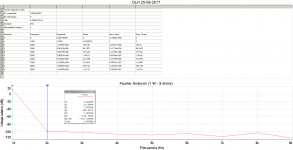 Fourier Analysis at 1W 8 ohms.png29.5 KB · Views: 7,436
 -
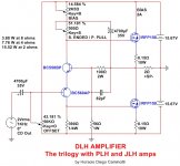 DLH Amplifier.jpg119.7 KB · Views: 7,758
 -
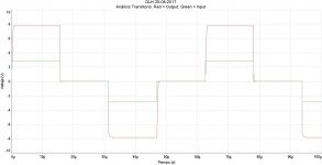 Transient Analysis.jpg275.7 KB · Views: 7,410
 -
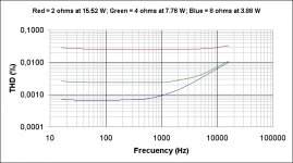 THD vs Frecuency.jpg135.6 KB · Views: 6,577
 -
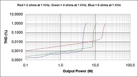 THD vs Output Power.jpg142 KB · Views: 6,390
 -
 PSRR vs Frecuency.jpg248.4 KB · Views: 4,810
 -
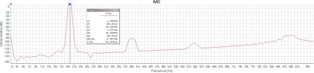 IMD at 2 ohms.jpg462.5 KB · Views: 4,525
Wow - very nice simple circuit Diego with great performance!
What's the DC stability like - both Iq and output voltage?
What's the DC stability like - both Iq and output voltage?

Many thanks Jonathan Bright, Bonsai and Ketje.
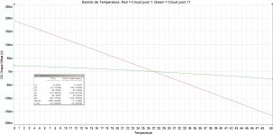
In relation to compensation, I had thought something like this:

I have not tried this same subcircuit, although in simulations it shows perfect compensation with temperature.
The circuit of the first post is a basic circuit. As it is shown in the first post has been tested in the videos. Everything can be improved, although as well as it is performs in impressive form.
Regards
In relation to compensation, I had thought something like this:
I have not tried this same subcircuit, although in simulations it shows perfect compensation with temperature.
The circuit of the first post is a basic circuit. As it is shown in the first post has been tested in the videos. Everything can be improved, although as well as it is performs in impressive form.
Regards
Last edited:
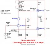
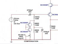
One possibility to attempt to partially compensate for a variation of the output offset with the variation of the supply voltage could be as follows:

While that resistance could increase Johnson's noise in a sensitive part of the circuit, it would also increase the input impedance of the circuit by a ratio of 6 to 8 times the current values.
This resistance could be between 150 K and 180 K approx.
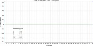
This has also not been tested, although in simulations reduces variations by a factor of around 2, relative to the first circuit.
Regards
While that resistance could increase Johnson's noise in a sensitive part of the circuit, it would also increase the input impedance of the circuit by a ratio of 6 to 8 times the current values.
This resistance could be between 150 K and 180 K approx.
This has also not been tested, although in simulations reduces variations by a factor of around 2, relative to the first circuit.
Regards
Last edited:
Last schematic makes no sense.Redraw it for a more usual look.
Mona
Excuse me, but your subcircuit is not like the one I posted 😕. Check it out, since it's not like mine 🙄. In your schematic you are connecting - V with ground, among other things ---> Booooommmmm !!! 😛.
Anyway, this subcircuit could be arranged visually so that everyone can understand it better 🙂.
Regards
Last edited:
Member
Joined 2009
Paid Member
Hugh Dean has posted something like this a few years ago and so did Broskie. Strange thng is I never saw anybody build it yet. Diego, now pressure is on you to build 😀
The circuit is working perfectly. You can see my videos from the first tests. Tested with very bad speakers sounds beautiful.
I do not know what these people have done in relation to configurations that might be similar to mine. I only know that it far exceeds my expectations, although the schematic is not very flexible when designing it, compared to others.
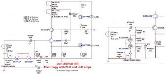
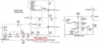
I'm surprised no one has ever used a scheme like this, yet. My design employs a "rustic vertical differential amplifier". If the output is set in perfect push pull configuration, using two similar paired N channel mosfets, H2 cancellation is excellent and the distortion residue is extremely low. It is of total simplicity but its parameters of quality are enormously surprising.
I built the JLH version Update and, I can assure that compared under the same speakers, my circuit performs several times better than the JLH.
It does not mean that the JLH dislike me. Simply, my circuit reproduces much more realistic, without annoying wheezes, with greater bandwidth than the JLH.
I had no chance to build the PLH, yet.
Regards
I do not know what these people have done in relation to configurations that might be similar to mine. I only know that it far exceeds my expectations, although the schematic is not very flexible when designing it, compared to others.
I'm surprised no one has ever used a scheme like this, yet. My design employs a "rustic vertical differential amplifier". If the output is set in perfect push pull configuration, using two similar paired N channel mosfets, H2 cancellation is excellent and the distortion residue is extremely low. It is of total simplicity but its parameters of quality are enormously surprising.
I built the JLH version Update and, I can assure that compared under the same speakers, my circuit performs several times better than the JLH.
It does not mean that the JLH dislike me. Simply, my circuit reproduces much more realistic, without annoying wheezes, with greater bandwidth than the JLH.
I had no chance to build the PLH, yet.
Regards
Last edited:
The circuit was first described by Christopher Rush in 1964.
It is a series LTP, one single current, very fast and high gain.
It has two outputs, in antiphase, functionally like a tube concertina phase splitter.
Ideal for a quasi amplifier driver and transconductance set with a single inter-emitter resistor.
Essentially it is an emitter follower driving a common base.
The circuit was first used commercially by Tomlinson Holman in the 1973 NAD 3020 phono preamplifier which established a very high reputation for decades.
Nice circuit, Horacio!! However, nothing is new under the sun but you should be proud that this does not detract from your clever implementation of a quasi drive for a power amplifier. Who knows, you could be the next Spanish Pass!
HD
Last edited:
an unusual way to present the squarewave tests. Does the stopping and starting @ the zero volts reveal any extra information useful to a designer?
Could this circuit be used with a high performance opamp wrapped up into a composite with global feedback?
Thank you very much, Hugh, for the valuable information on precedents related to the subject. I will try to find them and see if there are similarities with what I post here.
AndrewT: Could you give an outline of what you would try to do? I can not see the need to use an OPAMP, unless I do not understand you.
The basic idea was to keep design as simple as possible, maximizing performance, as far as possible.
The weak point could be the offset, although that is easily solvable. Otherwise, the design reaches more than interesting parameters.
Regards
The composite using either a gain stage, or a Current Buffer for the second stage usually offers increased performance.
W.Jung has written extensively on this. Our Member Tomchr has produced such a composite and to date his achieved performance is way above what any plain Jane 3886 could achieve.
W.Jung has written extensively on this. Our Member Tomchr has produced such a composite and to date his achieved performance is way above what any plain Jane 3886 could achieve.
I don't understand, where is it different ?Excuse me, but your subcircuit is not like the one I posted 😕. Check it out, since it's not like mine 🙄. In your schematic you are connecting - V with ground, among other things ---> Booooommmmm !!! 😛.
Anyway, this subcircuit could be arranged visually so that everyone can understand it better 🙂.
Regards
Mona
Attachments
- Home
- Amplifiers
- Solid State
- DLH Amplifier: The trilogy with PLH and JLH amps