Cant get it to work correctly!
What is going on?????
The clock is powered by a 12v toroidal, the tcxo is getting 5vdc as it should, I've removed the 2 old oscillator caps to ground and the resistor, theres no solder splashes or dodgy soldering and the in/out is correct but when I power the player (NAD C515BEE) the transport goes crazy. Its spinning eratically and clicking as if it doesn't know what to do............
Any suggestions??
Anyone had problems with their diykits clock??
One question, where have you connected the new clock ground.
there's only 2 output cables on the clock, 1 to the IC input and a return from the IC to the clock. Should there be a seperate ground?
The return is the ground, it is the ground plane on your new clock circuit. Foreign translations sometimes aren't clear. The return should be connected to a ground point close to the chip you are feeding the clock to, or the signal can get into other circuits.
Where do you have the return connected now.
Where do you have the return connected now.
The return is the ground, it is the ground plane on your new clock circuit. Foreign translations sometimes aren't clear. The return should be connected to a ground point close to the chip you are feeding the clock to, or the signal can get into other circuits.
Where do you have the return connected now.
I replaced the old 2 pin oscillator with the clock, so I assumed the clock input/output goes to the same old positions?
No, the new clock is self contained, it takes no input from the chip. Connect the clock output to the Xin and the return to a ground near the chip. That's it. I'm hoping nothing is damaged.
I tried to look at the clock on their website but the page wont load.
I tried to look at the clock on their website but the page wont load.
Last edited:
No, the new clock is self contained, it takes no input from the chip. Connect the clock output to the Xin and the return to a ground near the chip. That's it. I'm hoping nothing is damaged.
I tried to look at the clock on their website but the page wont load.
You're a GENIUS!!!!
Thanks for that, the disc reads perfect and the toc is correct.
The only problem now is I have no output????
I'll try rectify that in a mo............
Ta
Well...............
The clock is working perfectly and spinning the disc and reading it correctly but there is now no output. I've checked nearly everything apart from the signal from the Toshiba TC94A54MFG-001 IC to the dac. How do I do this?? have I killed the toshiba??
Ta
The clock is working perfectly and spinning the disc and reading it correctly but there is now no output. I've checked nearly everything apart from the signal from the Toshiba TC94A54MFG-001 IC to the dac. How do I do this?? have I killed the toshiba??
Ta
I'm definitely not a genius. It might be toast, but probably not.
I could not find the chip's datasheet, but it is supposed to have built in DA converters. If you can find those output pins you could check it with a dmm. If you have an outboard DAC unit you could see if the spdif output is functioning. Otherwise, it will take an o-scope. Also worth noting, the chip is 3.3v,the clock is 5v. Check with the clock seller about the possible need for reducing the clock signal voltage.
Good luck, Bill
Also, if you still have the original parts you could reinstall them and check the operation before you go any further.
Also, if you still have the original parts you could reinstall them and check the operation before you go any further.
The original parts were 2 tiny ceramic caps and a resistor which I discarded when removed, so that's not possible. I don't even know the values to replace them.
I shouln't really be messing with stuff I have no idea about. Shame, it keeps costing more money to fix. I've now spent 3 times the amount of the initial cost of the brand new player on bits and bobs and all I've gained is a non worker.
Boooo.
I'm in need of testing the output of the IC, there's little info on the net apart from this pdf here: http://www.toshiba.com/taec/components/Generic/05B04_TC94A5460MFG.pdf
As I have no output, do I need to check pins 57 to 60?? and/or any others to see if I've cream crackered the IC???
Thanks
As I have no output, do I need to check pins 57 to 60?? and/or any others to see if I've cream crackered the IC???
Thanks
I just did a quick test on my player and found the strangest thing........ When the player is on, the output turns to ground, but when the board is removed with no power, it's not!
What the hell is going on??????
What the hell is going on??????
Super spankin great......
Fantastic...........................
After all that it was a silly little break in the circuit.
The circuit was broken from the Toshiba IC on the MCLK track to the dac where the old oscillator sat, oops, too much heat.
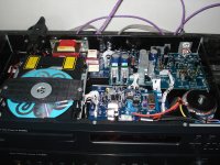
Good stuff, so after 6 weeks, 67 replacement caps, 3 Class D regs, opamps, CMC silver rca's, alot of dampening, a re-wire, a clock kit, a 12v toroidal, reels of mundorf solder, removal of un-needed bits, burnt fingers and alot of shouting, it's finished and the brucey bonus is............. it sounds great!
There's a photo attached if anyone's interested.
Chow fa now
Fantastic...........................
After all that it was a silly little break in the circuit.
The circuit was broken from the Toshiba IC on the MCLK track to the dac where the old oscillator sat, oops, too much heat.
Good stuff, so after 6 weeks, 67 replacement caps, 3 Class D regs, opamps, CMC silver rca's, alot of dampening, a re-wire, a clock kit, a 12v toroidal, reels of mundorf solder, removal of un-needed bits, burnt fingers and alot of shouting, it's finished and the brucey bonus is............. it sounds great!
There's a photo attached if anyone's interested.
Chow fa now
Attachments
I think we've all had those moments.. Glad you found the problem.
What do you think of this external clock as compared to the original crystal/internal oscillator?
What do you think of this external clock as compared to the original crystal/internal oscillator?
I think we've all had those moments.. Glad you found the problem.
What do you think of this external clock as compared to the original crystal/internal oscillator?
It's probably the most cost efficient clock upgrade out there, I'm not saying it's anywhere as good as those reference clocks which cost upto 20 times more but I can gladly say it's a huge improvement over the standard oscillator.
Chuffed!
I knew you would get it straightened out, you now are a bona fide, fearless, DIY solder slinging crazy man, just like the rest of us.
Best regards, Bill
Best regards, Bill
I knew you would get it straightened out, you now are a bona fide, fearless, DIY solder slinging crazy man, just like the rest of us.
Best regards, Bill
I like that, made me laugh!!!
I like that, made me laugh!!!
Me too.. 😛
At some point I'll have to check out that oscillator kit for my shigaclone..
- Status
- Not open for further replies.
- Home
- Source & Line
- Digital Source
- diykits.com.hk clock help