Sorry to (further) derail the thread... I have dipped my toe into it too, but stopped short because I didn't find appropriate parts/symbols...
Where to look for stuff like rotating switches (elma, grayhill etc.)?
Where to look for stuff like rotating switches (elma, grayhill etc.)?
Right! What I am trying to do is a PCB that can be mounted with either standoffs or flipped around fixed on the bridge hole.I do not understand why you say the bridge can only mount on the top.
It is fun indeed! 😎By the way, I also started designing pcbs a short time ago. I think it's great fun. It is like a computer game for nerds. 🤓
i make universal psu based on diy audio v3 using part that easily available in asian countries especially in southeast asia where i come from, for example using center tap transformer instead of dual transformer. bridge rectifier using GBPC3510W where is easily available as used part and it is cheap less than 1 usd (genuine vishay!).

https://oshwlab.com/annas.myrmidonia/universal-power-supply-for-audio-amplifier
you can use link above to edit schematic, components placement and directly order from jlcpcb for 6 usd for 5 pcs pcb (shipping around 10 usd) (rest a sure, i dont get any money when you are using my link).
https://oshwlab.com/annas.myrmidonia/universal-power-supply-for-audio-amplifier
you can use link above to edit schematic, components placement and directly order from jlcpcb for 6 usd for 5 pcs pcb (shipping around 10 usd) (rest a sure, i dont get any money when you are using my link).
Last edited:

and this is ground loop breaker based on elliott work. using same bridge rectifier and worked directly with psu above because mounting hole doesnt connected with ground. GE is Ground Earth (to chassis) GA is Ground Amp (to psu ground). https://oshwlab.com/annas.myrmidonia/ground-loop-eliminator

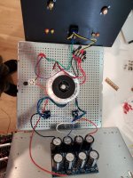
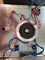
Hey yall. I'm doing an Aleph J build. I'm just testing the psu, and getting 56v just on the positive side of the psu board. 0 from negative. I know it's supposed to be 28 and 28. I'm sure I botched something. Anyone had something similar happen? Thank you!!
Pictures would be very helpful. Show how your transformer is hooked up to the rectifiers and the rectifiers hooked up to the filter portion of the board.
@pestoman
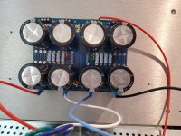
Looks like you've got red for your positive rail, and green for your negative rail. If the green LED lit... you don't have 0V to that side of the board.
In addition to 6sX7's advise, be sure you are measuring properly. If you are measuring between the two outermost sets of contacts... you will read 56V.
Just in case...
I'm just testing the psu, and getting 56v just on the positive side of the psu board. 0 from negative.
I am getting red and green lights
Looks like you've got red for your positive rail, and green for your negative rail. If the green LED lit... you don't have 0V to that side of the board.
In addition to 6sX7's advise, be sure you are measuring properly. If you are measuring between the two outermost sets of contacts... you will read 56V.
Just in case...
Attachments
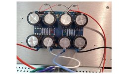
Nope I'm stupid. You're totally right, both leds were lit, I was measuring AC. DC is 25V positive on red side, negative on the green. Now I am curious to know why the positive side sees AC current. Thanks a bunch to both of you.
^ 56VAC would be very, very odd. Are you sure there's not a decimal in there... and/or that it's not showing mV, or that you're measuring in the correct spot? My best guess (so far) is that you may be measuring the ripple and not reading the meter correctly. A quick and dirty sim of that type of PSU shows 103mV of ripple with a very, very light load... just your resistors / LED. I get 53mV with an estimate of two amp channels loading the PSU. Not too far off... and I used big fat estimates. I have a rough time picking up mV level AC with a handheld DMM, but yours might do a really wonderful job. YMMV.
So... I'm not saying that's the reason, and that you're having another measurement issue, but it's an idea.
Noted that you're closer to 25VDC than 28DC. 🙂 If not, my next questions were going to be around your mains voltage and if you got a 20VAC instead of 18VAC transformer. Awesome progress.
Check that AC measurement one more time... maybe post a pic of the DMM and where your probes are placed if you don't get it sorted.
Not particularly relevant, but also... that's why a Variac or similar is a very useful thing to test PSUs ... if you had actually done something more severe, and if you really did have 56VDC on the positive rail ... those 35V caps ain't rated for that. They likely wouldn't have "blown up" when hit with that for a little while, but it wouldn't have been great for them... and worst case may have hurt them.
Hello gents,...I'm in the process of building the Wolverine. Boards almost finished and I'm about to start bulding the power supply. I've got 2 transformers of 500 VA with each transformer having 2 secondaries, 42V each secondary. I have 4 chassis mount kbpc rectifiers. 1 for each secondary. I'm looking at 2 filter caps per rail of about 10.000 uF / 80V. I need some advise on which PSU board I require. i saw the diyaudiostore V3 is sold out. Any ideas?
thx in advance
w.
thx in advance
w.
If you'd like a fairly standard CRC filter (similar to the Universal PSU design) there are a number of excellent adaptations out in the wild.
A recommended first stop would be @rhthatcher's Etsy store. Take a look at his V8 boards. In your case, the V8 4 (caps per rail) would be just fine. I know the Wolverine has very good PSRR, but 20kuF total per rail or 20kuF for each C in the CRC?
https://www.etsy.com/listing/1431642860/monoblock-class-a-v8-crcrc-dual-rail?click_key=db6eeddcdc028aa45e0791799cc11d63d3d111d4:1431642860&click_sum=dbb88ff8&ref=shop_home_recs_12&sts=1
https://www.etsy.com/listing/1445849437/dual-mono-class-a-w12-crcrc-dual-rail?click_key=2e74cec384a9078f0d0f8e0e6d370018f010ddb8:1445849437&click_sum=0a51b5bc&ref=shop_home_recs_13&sca=1&sts=1
FWIW, I still haven't landed on what PSUs I'll be using for my pack of Wolverines...
Edited - Deleted section re: using a jumper. 👎🙄😵🤦♂️
Last edited:
Hi,
For the snubber circuit, are theses resistors suitable ? Which ones should I choose for an Aleph J ?
I choose for toroidy 500VA/2x18V 240V
"Torroidy 500VA, 240V primary, dual 18V secondaries
Cx: 10nF
Cs: 150nF
Rs: 7Ω / 7Ω"
https://www.mouser.fr/ProductDetail/YAGEO/MFR50SFTE52-7R15?qs=UFD7vfw3J8rsK0PK07LJqg==
https://www.mouser.fr/ProductDetail/KOA-Speer/CF1-2CT52R7R5J?qs=M2dwKwyQZFc3OCjNYJ21RA==
What are the optional resistors used for? I didn't understand. Do I need it?
Yes, I'd go with these snubber-values. (looking up Yeffyoung's history you'll see he is quite trustworthy)
The r_Optional 1-6 give you the possibility to tune your c_R_c even finer… use 4 x 0.47r = 0.1r as per firstwatt, or lower the resistance(?) by using more of them, or increase the „wattage“ by using 7 x 0.8r…
You just have many more options to make it fit as precisely as needed.
The r_Optional 1-6 give you the possibility to tune your c_R_c even finer… use 4 x 0.47r = 0.1r as per firstwatt, or lower the resistance(?) by using more of them, or increase the „wattage“ by using 7 x 0.8r…
You just have many more options to make it fit as precisely as needed.
Last edited:
Thank you very much for answering me.
With the snubber circuit, do you know if I should keep the thermistors and the C9 capacitor offered here :
From DIY Aleph J: A Build Guide
"Second, in order to faithfully duplicate the power supply shown on the Aleph J schematic, we will need to add two terminal blocks that will attach to the chassis baseplate. These terminal blocks will be used to connect thermistors (to limit inrush current when the amp is turned on), as well as a capacitor for spark suppression across the AC switch and noise filtering. (If some or all of this vocabulary is over your head, have no fear, we'll explain in more detail in the power supply build post). So, to sum up, here's what we changed or added to the Universal Power Supply BOM :
- deleting D1-8, all the optional resistors, R11-12, all the snubber parts
- add two terminal blocks, three thermistors, one line capacitor (call it C9)"
Yes, keep them.
The thermistors act as inrush-limiter, the cap prevents sparks.
(Instead of the thermistors, you could add a dedicated soft-start-circuit, which is offered in the store, or a even more sophisticated circuit like mark johnson‘s… elegant but complex…)
The thermistors act as inrush-limiter, the cap prevents sparks.
(Instead of the thermistors, you could add a dedicated soft-start-circuit, which is offered in the store, or a even more sophisticated circuit like mark johnson‘s… elegant but complex…)
what is the difference between using thermistors and softstart circuit? I've the softstart board with the speaker protector one.
Some have told me that thermistors are safer than softstart...
From DIY Aleph J: A Build Guide
"Step #1: Snap Off the Diode Rectifier Section
The DIYAudioStore Universal Power Supply boards include a section for building a full wave bridge rectifier out of discrete parts. We're not going to use that portion of the board, because we are using monolithic bridge rectifiers, which package in a nice, compact component the four diodes and associated bits that make up a full wave rectifier.
So, snap that section off and discard (or use it to practice your soldering skills with some extra resistors and wires before discarding it)."
Last edited:
Both work. Thermistors are fewer parts, less money, and simpler.
The thermistor is always in the circuit, it is a single part and so, yes, they're safer than a soft-start.
OTOH, the thermistor always is a (small) resistor in the circuit and as such a (small?) heat source in the chassis...
A softstart-board acts as, well, a soft-start, and then switches itself out of the circuit. This is its advantage, but it could be built wrongly or fail some day.
(Here's from a datasheet:
The NTC thermistor […] limits surge current by functioning as a power resistor which drops from a high cold resistance to a low hot resistance when heated by the current flowing through it.
)
@6L6 always to the point in as few letter as possible! (and even leaves open the question if these criteria are pro or contra Thermistors 😀
Last edited:
- Home
- Amplifiers
- Power Supplies
- diyAudio Power Supply Circuit Board v3 illustrated build guide