My F5 implementation is like this. I probably made a mistake but I don't know what is it. I can provide more photos if you ask.
In general, if I summarize;
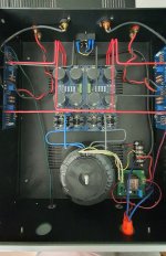
I used F5v3 pcb and universal power supply both from diy audio store. Audio Grade 18v X 2/400va transformer from Toroidy and a China origin soft start. On power supply unit, I used MBR20200 schottckys and 4pcs 50v 10.000uf capacitors per rail. Ground line connected to chassis via CL60. When I checked all the wiring, only ground to chassis connection is this.
I see 21.5v dc on each rail in the voltage measurement I made 10 minutes after powering up. Bias is set to 0.55v because vibration increases significantly at 0.60v.
I also realized that on https://www.diyaudio.com/community/...cuit-board-v3-illustrated-build-guide.244788/ page, I soldered all the legs of MBR20200ct to the board but on the illustration guide only two legs are soldered. Is this a mistake?
In general, if I summarize;
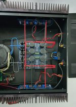
I used F5v3 pcb and universal power supply both from diy audio store. Audio Grade 18v X 2/400va transformer from Toroidy and a China origin soft start. On power supply unit, I used MBR20200 schottckys and 4pcs 50v 10.000uf capacitors per rail. Ground line connected to chassis via CL60. When I checked all the wiring, only ground to chassis connection is this.
I see 21.5v dc on each rail in the voltage measurement I made 10 minutes after powering up. Bias is set to 0.55v because vibration increases significantly at 0.60v.
I also realized that on https://www.diyaudio.com/community/...cuit-board-v3-illustrated-build-guide.244788/ page, I soldered all the legs of MBR20200ct to the board but on the illustration guide only two legs are soldered. Is this a mistake?
Attachments


But no, i did some digging and found that MBR20200ct is different than FFPF30 which is using illustrated build guide of ups.
Reverse the blue leads to the diodes. I suspect you have the secondaries in opposite phase.
Last edited:
Thank you @6L6 I'll try today. On the other hand, I'm also started to think there might be a problem with the multimeter. I discovered that there was a 50mv difference between the two multimeters. It may have caused incorrect adjustment during bias adjustment. I'm thinking of buying a third multimeter. Is there a brand/model you'd recommend?

@6L6 I've changed the polarity of transformes secondary and also reset all bias settings and re-adjust again. But unfortunately nothing is changed. My transfomer is still ringing. Of course, since I updated the bias setting with new multimeters, some of the sounds I normally get when I get close to the speaker have improved. However, there is still a hum heard from up close on the bass side and the ringing sound in the transformer continues. While I can hear the hum sound in the bass section from a speaker with a sensitivity of 91db, I naturally cannot hear it from a speaker with a sensitivity of 90db. But I want to be sure why I am getting this sound. Another issue that comes to my mind is the mains electricity. Could there be a frequency problem there? Is there any way you can measure or understand this? Or could there really be a problem with Toroidy-made transformers?
@6L6 I think I found my problem, but I also need your advice.
The transformer I bought from Toroidy is not center tapped, it has dual 18v outputs. The smallest voltage difference between the ends is 4v. After the outputs are rectified with the bridge, when we connect the negative ends on the UPS board, I think there is an unwanted short circuit here. I am not sure if I am right in this thought. I think that the transformer starts to whine when the current required by the amplifier is loaded along with the short circuit. And of course it produces some heat on transformer after 1 hour of work.
The transformer I bought from Toroidy is not center tapped, it has dual 18v outputs. The smallest voltage difference between the ends is 4v. After the outputs are rectified with the bridge, when we connect the negative ends on the UPS board, I think there is an unwanted short circuit here. I am not sure if I am right in this thought. I think that the transformer starts to whine when the current required by the amplifier is loaded along with the short circuit. And of course it produces some heat on transformer after 1 hour of work.
After voltage measurement, the final state seems to be 0-18-22-40, but I requested exactly double 0-18 windings. In theory, since I will use 0-18 and 22-40, both are 18 volts. And there seems to be no problem with that. But I think the ends that were combined for 0v after rectification caused a short circuit.
^ Would you please provide the exact model of transformer from Toroidy. Take a picture clearly showing the the label with the identification of the primary and the secondary colors.
I am not a licensed electrician, but I what I would recommend as a start is to:
Take your mains earth ground from the PEM and run it directly from the PEM to the chassis with a thick, short wire. You have it running to your terminal block and through the CL-60 to chassis along with your transformer shield. IMO, you should not have the thermistor between safety ground and the chassis. Measure and ensure that you have a very low resistance from the safety ground to the chassis. Scrape some paint if needed.
Run the transformer screen to a separate point on the chassis without the CL-60 in the middle.
The thermistor, I assume, was meant to be your audio ground lift. Leave it out for the moment.
After you post the picture of the transformer label, we can diagnose further.
Sourcing matched JFETs for this build (regular F5 in stereo config) and have a couple of options:
- Toshiba 2SJ74 + 2SK170 match to 0.1mA (6.0 - 8.0 mA range "BL" "B")
- Toshiba 2SJ74 + 2SK170 match to 0.1mA (8.0 - 11.0 mA range "BL" "B")
I guess the 8.0 - 11.0 mA pair would be a better pick here? Am I on the right track?
Thanks!
- Toshiba 2SJ74 + 2SK170 match to 0.1mA (6.0 - 8.0 mA range "BL" "B")
- Toshiba 2SJ74 + 2SK170 match to 0.1mA (8.0 - 11.0 mA range "BL" "B")
I guess the 8.0 - 11.0 mA pair would be a better pick here? Am I on the right track?
Thanks!
- Home
- The diyAudio Store
- diyAudio F5 Build Guide