OPS is first ...
I'm doing it's build guide.
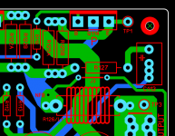
You got the OPS's specifics right. (most of them). Sprint's exportable component
list is quite handy. Never used it.
-DIYaudio is a component instead of many parts.
- (-V) was too close to a UMS hole ... imagine a shaky hand and a screwdriver.
-Zobel is overkill creep now.
-PSU ground is closer to a UMS hole and centered to the caps, it can be.
-UMS chassis ground plane beneath the IPS.
On the 2 IPS's , I did slight design changes that will greatly make sourcing
easier.
Both the Spook and Wolverine now have LTP and cascode Vce requirements
of just 30-40V. Either of the devices can be +/-60V devices. Common value , greatly expands sourcing.
Spook's VAS adjust had 110V across the trimmer.
Now the Hawksford cascode voltage is split between R18/19 (55V instead
of 110).
24 V front end operation also makes the Spook need less offset for P/N
imbalance in the LTP's. An added plus for this design change.
My signature of "less is more" is no BS
.... these amps(IPS's) are VERY durable , with just 13/14 devices. Easy to wrap your head around.
Just as with SMD (Kypton and Hellraiser) , modular is new ... but I know they
will love it. What other project can they just run the OPS independantly ??
None !!
OS
I'm doing it's build guide.
You got the OPS's specifics right. (most of them). Sprint's exportable component
list is quite handy. Never used it.
-DIYaudio is a component instead of many parts.
- (-V) was too close to a UMS hole ... imagine a shaky hand and a screwdriver.
-Zobel is overkill creep now.
-PSU ground is closer to a UMS hole and centered to the caps, it can be.
-UMS chassis ground plane beneath the IPS.
On the 2 IPS's , I did slight design changes that will greatly make sourcing
easier.
Both the Spook and Wolverine now have LTP and cascode Vce requirements
of just 30-40V. Either of the devices can be +/-60V devices. Common value , greatly expands sourcing.
Spook's VAS adjust had 110V across the trimmer.
Now the Hawksford cascode voltage is split between R18/19 (55V instead
of 110).
24 V front end operation also makes the Spook need less offset for P/N
imbalance in the LTP's. An added plus for this design change.
My signature of "less is more" is no BS
.... these amps(IPS's) are VERY durable , with just 13/14 devices. Easy to wrap your head around.
Just as with SMD (Kypton and Hellraiser) , modular is new ... but I know they
will love it. What other project can they just run the OPS independantly ??
None !!
OS
Attachments
KSC1008C and KSA708C
Screw the harder to source 992/1845.
KSC1008C and KSA708C , designs are set for these.
Might still need the 1845 for Q7/12 wolverine.
These BS constraints will pass , SMD will save us !!
OS
Screw the harder to source 992/1845.
KSC1008C and KSA708C , designs are set for these.
Might still need the 1845 for Q7/12 wolverine.
These BS constraints will pass , SMD will save us !!
OS
Have I deviated ??
I'm scared that this (it is easier than Badger) might be too much for
DIYA ??
Looking at Pass , this is "somewhere else".
In light of the Badger , in the same realm. But different.
If I make the build guide "human" , I might get away with this.
I assure you , for 13/14 devices ... you will bring people in front of your
system and say "check this out ". They might be very impressed.
OS
I think that most of the typical DIY's will build whatever has the best Documentation and specifications.I'm scared that this (it is easier than Badger) might be too much for
DIYA ??
Looking at Pass , this is "somewhere else".
In light of the Badger , in the same realm. But different.
If I make the build guide "human" , I might get away with this.
I assure you , for 13/14 devices ... you will bring people in front of your
system and say "check this out ". They might be very impressed.
OS
Also alot of us have plenty of small signal transistors on hand already.
I for one have hundreds if people are really stuck send me a pm.
I am reckoning the human vs project aspect now.
Very few would do this ?? I want all to have the very best.
Only what I would accept - I'm very picky.
OS
Very few would do this ?? I want all to have the very best.
Only what I would accept - I'm very picky.
OS
Last edited:
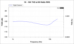
Honey Badger - Distortion Plot
I thought I might post this as a reference.
These are the distortion numbers that I'm getting from my Honey Badger.
Plot shows the distortion 1K to 16K at 80 watts RMS using 6 harmonics for each of the THD calculation points.
I am reckoning the human vs project aspect now.
Very few would do this ?? I want all to have the very best.
Only what I would accept - I'm very picky.
OS
I thought I might post this as a reference.
These are the distortion numbers that I'm getting from my Honey Badger.
Plot shows the distortion 1K to 16K at 80 watts RMS using 6 harmonics for each of the THD calculation points.
Attachments
who's stuck ??
Not good.
I'm not stuck , In fact ... I am 'unstuck".
modular ...
This is now totally thought out. It will be a fully modular offering with
future upgrades.
I now am deadly ... I dream new IPS's.
OS
Not good.
I'm not stuck , In fact ... I am 'unstuck".
modular ...
This is now totally thought out. It will be a fully modular offering with
future upgrades.
I now am deadly ... I dream new IPS's.
OS
Last edited:
I thought I might post this as a reference.
These are the distortion numbers that I'm getting from my Honey Badger.
Plot shows the distortion 1K to 16K at 80 watts RMS using 6 harmonics for each of the THD calculation points.
Do you realize ... that the wolverine with this layout might be nearly sub - PPM
if your badger results are THAT.
For this design , I'm aiming for 3-4R and 5 ppm. This Wolverine does 1ppm
20Hz to 15K ... at 100V p-p .
OS
Well I have Bob Cordell's Distortion Magnifier. It arrived yesterday it apparently will increase Distortion by up to 20dB so it can be measured.Do you realize ... that the wolverine with this layout might be nearly sub - PPM
if your badger results are THAT.
For this design , I'm aiming for 3-4R and 5 ppm. This Wolverine does 1ppm
20Hz to 15K ... at 100V p-p .
OS
The current loopback distortion of my QA401 is around 0.006% so as the wolverine will be lower than this I'll have to use it otherwise it will be impossible to measure.
Yer' gunna need it.
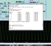
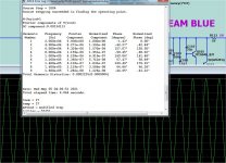
Pass class A people can drip and drool ... (below) is 25 W class A EF3 pertformance at 3R.
Also , 100V p-p at 3R ... (below 2).
Evil nested NFB , what blasphemy. I still get my PPM.
PS - wolverine at 56p/220p is how far you can push it. slight ringing =
68 dg margin. But , 2ppm 100v.
Pass class A people can drip and drool ... (below) is 25 W class A EF3 pertformance at 3R.
Also , 100V p-p at 3R ... (below 2).
Evil nested NFB , what blasphemy. I still get my PPM.
PS - wolverine at 56p/220p is how far you can push it. slight ringing =
68 dg margin. But , 2ppm 100v.
Attachments
Last edited:
Approved ...
That is impressive.
Wolverine is "top dog" , my pitbull approves. a lot of possibilities with this IPS.
OS
That is impressive.
Wolverine is "top dog" , my pitbull approves. a lot of possibilities with this IPS.
OS
Question for you OS.
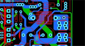
I see that you did not run copper top and copper bottom to the output.
Why?
Was this so the NFB received a more accurate voltage as it was closer to the output etc.
If so I had an idea to help improve this.
If you open my attached layout file you'll see I switched C1 and C2 and then made the NFB not a through hole and then isolated it from the copper top.
Have a look that the top copper zone. Its has a small circular isolation ring from the rest of the top copper.
Would this help what you are tying to achieve.
Attachments

You put the top layer on NFB at the source. You DON't do that.
It is 8mm wide single side. The NFB through-hole take off is derived from another
layer. It is KT's "canada" run to the IPS. 8mm is 20+ A single sided.
This is understandable , not thinking in 2 layers.
How it was is freakin' ideal.
PS - having the top side as the NFB takeoff is not as ideal.
OS
It is 8mm wide single side. The NFB through-hole take off is derived from another
layer. It is KT's "canada" run to the IPS. 8mm is 20+ A single sided.
This is understandable , not thinking in 2 layers.
How it was is freakin' ideal.
PS - having the top side as the NFB takeoff is not as ideal.
OS
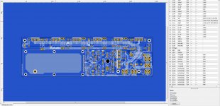
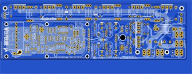
Alignment Fixed
The Alignment was still out, so I fixed it for you.
Everything is now accurate and on grid. No extra place values etc...
I only tweaked the hole positions of the Main PCB, IPS mounts and SIP1 pitch.
I hope that works for you.
The Alignment was still out, so I fixed it for you.
Everything is now accurate and on grid. No extra place values etc...
I only tweaked the hole positions of the Main PCB, IPS mounts and SIP1 pitch.
I hope that works for you.
Attachments
Last edited:
The Alignment was still out, so I fixed it for you.
Everything is now accurate and on grid. No extra place values etc...
I only tweaked the hole positions of the Main PCB, IPS mounts and SIP1 pitch.
I hope that works for you.
How did you find a problem ? (below) I cant...
perfect fit.
OS
Attachments
How did you find a problem ? (below) I cant...
perfect fit.
OS
No its not. Watch the youtube video.
Please look at post 814.
Its all fixed in the attached file.
Attachments
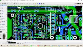
The holes might line up between the main PCB and the IPS but the measurements between the holes on the main boad that you posted isn't right. They are slightly out of alignment. Just use the measurement tool and check it.
I fixed all the issues in the file I attached.
I fixed all the issues in the file I attached.
When I do amp layout one of my main concerns is to make FB line as short as possible. I don't see it here.
My suggestion is to move it like attached, but still nothing to write home about
Ask KT about that.
- You might not get the PPM performance you expect.
-Just making it short is BS. Cancellation on it's return (and the total loop)
After 50 papers and 100 schemas ( 10 PM's) there is a type of magic here
which does not involve the shortest NFB path.
I respect your symmetric CFA thread , it will be assimilated by the BORG.
The Hellraiser(SMD) will have DADOD in it .... 😀
OS
- Home
- Amplifiers
- Solid State
- DIYA store "Wolverine" (Son of Badger) .... suggestions ??