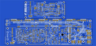
Main board , Spook , and Wolverine are storebound.
You can batch check any IPS for creep in 30 seconds.
Stuart showed that a little can go a long way for a pretty board.
JK's original Spooky was the coolest audio board I ever populated.
(below) I'm doing the Spook and Wolverine now (complete with component
extended info).
Going full modular is the way . You can compartmentalize IPS/OPS builds.
I already use divided numbers , IPS's are R1,2,3 OPS's are 101,102 ...
OPS and Wolverine have had 4 eyes on them .... just do component housekeeping.
Spook might need some eyes. 😀
PS - I'll post the 3 storebounds ...
OS
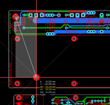
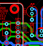
Isn't this trace too close to the hole?
Attachments

Who the heck snapped up all the ksa992FTA's in the world? Once again they're all gone.
Ive got a hold of a couple of hundred ksc1845FTA's, but missed out on the 992's.
Ive got a hold of a couple of hundred ksc1845FTA's, but missed out on the 992's.
Who the heck snapped up all the ksa992FTA's in the world? Once again they're all gone.
Ive got a hold of a couple of hundred ksc1845FTA's, but missed out on the 992's.
They are due in mid july. Isn't the FBU bulk type better? Isn't the pcb is designed for straight leads?
Why Hellraiser will be SMD ....
Like pandemic grifters stocking up on toilet paper , I had no TP for 4 months
last year ..... they will buy out the 992's.
Traces near holes ... most likely the two middle holes can be optional on an
IPS. Or plastic standoffs can be used.
OS
Like pandemic grifters stocking up on toilet paper , I had no TP for 4 months
last year ..... they will buy out the 992's.
Traces near holes ... most likely the two middle holes can be optional on an
IPS. Or plastic standoffs can be used.
OS
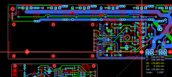
The Payload ..
Just about done.
OS
Just about done.
OS
Attachments
Last edited:
They are due in mid july. Isn't the FBU bulk type better? Isn't the pcb is designed for straight leads?
The FBU are backorder as wel. The FTA is knicked lead in ammo pack.
Most PCB's are designed for wider lead spacing then the FBU bulk parts have.
How do you feel about rotating C109 90 degrees and relocating it between C103 and Q104. This would provide easy access to the bias trimmer R109 from the top even with amplifier fully assembled and in chassis (assuming a side adjustment trimmer is used). Unless the existing arrangement already provides for adequate access.
The output end of the PCB i ment to face down. Outputs should be mounted around 1/3 up from the bottom of the heatsink.
Thank you OS, thank you Stuart and thanks to everyone who has been involved in this beautiful project!
Gaetano.
Gaetano.
How do you feel about rotating C109 90 degrees and relocating it between C103 and Q104. This would provide easy access to the bias trimmer R109 from the top even with amplifier fully assembled and in chassis (assuming a side adjustment trimmer is used). Unless the existing arrangement already provides for adequate access.
Outputs go down. R109 should be accessable.
OS
The FBU are backorder as wel. The FTA is knicked lead in ammo pack.
Most PCB's are designed for wider lead spacing then the FBU bulk parts have.
I see straight leads on the wolverine. Unless you are building something else.
To-92 pads on both IPS's were based on a 2.5mm pitch - (preformed leads).
I saw the lack of 992's. Sucks !!
The Wolverine Cascode (Q5/ 6) is common Base. Negates Cob , so use a ksa916Y PNP -10K stock -Mouser.
The 916 is lower Hfe , just get at least B grade BC546/556 for Q1-4.
You will have a real "beefy cascode" , 916 is a TO-92 (L)ECB.
Ksa916Y as the CCS(Q8/9) is no issue.
Hmm , actually Q5/6 see just 1/2 the neg. rail (32V) ,
BC638 is -60Vce ... and ECB ! it would work ! So could the KSP2907 (-60V-ECB)
Q7/12 - plenty of 1845's around !!!
Have to find a more closely matched P/N for the Spooky Cascodes.
Spook's cascodes see 47V C-E (60V rails). So ,
Only ECB in P/N compliments are KSC1008C and KSA708C. +/- 60V parts.
Mouser has 3-4K of each.
With these choices , 65V rails would be MAX !!
PS - Just thought of it .... You could use 24V zeners for the spooky regulators and drop Cascode C-E
to 30+V , good ! No servo IC on this spooky.
Edit - that works good , no HV semi's for either of these IPS's front ends. No semi see's more than 40V.
OS
Last edited:
Hi Pete
I have a question regarding your VAS active clamp, found in a previous design.
As I do not want to clutter this thread with obtrusive questions I sent you a personal message.
Would you care to answer it ?
Best
I have a question regarding your VAS active clamp, found in a previous design.
As I do not want to clutter this thread with obtrusive questions I sent you a personal message.
Would you care to answer it ?
Best
Alignment Issues
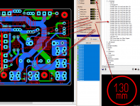
You might want to look at this YouTube Video
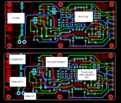
and the attached images. If you switch C2 to C1 you will have one continuous trace on the input without switching board sides. (see image 1)
Sprint Layout Tips Alignment Tips - YouTube
I'll take a closer look later if your like. Don't have time tonight.
Hi OS,Just about done.
OS
You might want to look at this YouTube Video
and the attached images. If you switch C2 to C1 you will have one continuous trace on the input without switching board sides. (see image 1)
Sprint Layout Tips Alignment Tips - YouTube
I'll take a closer look later if your like. Don't have time tonight.
Attachments
Last edited:
I see straight leads on the wolverine. Unless you are building something else.
knicked leads are in a straight line. But lead spacing is 2.54mm.
Outputs go down. R109 should be accessable.
OS
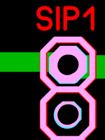
So the wording on the silk screen would be upside down?
That's depending on where you would be looking at it from.
Leaning over a heatsink from the side (typical) with your screwdriver ,
the screen would be right.
Perhaps , looking from the other side ... you are right.
OS
Leaning over a heatsink from the side (typical) with your screwdriver ,
the screen would be right.
Perhaps , looking from the other side ... you are right.
OS
Hi Pete
I have a question regarding your VAS active clamp, found in a previous design.
As I do not want to clutter this thread with obtrusive questions I sent you a personal message.
Would you care to answer it ?
Best
That clamp is either in D. Self's book , or even on Prof. Leach's symmetrical amp.
On a Blameless (Wolverine) , it acts like a temporary current source by
being triggered by the main VAS's Re current (overload). When it does that
, it's miller characteristics affect the main VAS.
The small resistor limited dissipation for the clamp (it could even blow).
The small 10pF cap stopped the ringing at clip.
All this so sloppy. Simple is sometimes better. the BAV21 has super low C ,
and takes all the current.
Other designs are so much more elegant , Spooky's Hawksford clips like
a tube amp , LED's clamp (and flash) the cascode. Kypton clamps
the LTP directly with 2 diodes. This won't work on the wolverine , High Z
CM/cascode ....
Thanks for your tip on R17 , was 15K ... now 2.7K. Slew back at 55V/uS.
O
Hi OS,
You might want to look at this YouTube Video
and the attached images. If you switch C2 to C1 you will have one continuous trace on the input without switching board sides. (see image 1)
Sprint Layout Tips Alignment Tips - YouTube
I'll take a closer look later if your like. Don't have time tonight.
I think it is ideal now(IPS).
I had to go through EACH component on all 3 boards. You did the ops nice.
Just a few additions.
I fixed R112/113 creep , C116 creep , and J3.
Q108 is unavoidable unless you shrink pads.
I fine tuned the UMS.
What I need now is documentation help.
As I said before , separate OPS/Wolverine/Spooky guides.
I'll pop out the rough text drafts for each. I'm not as good on embellishments.
OS
Thanks OS, I hoped that the video helped you and we can move forward with an accurate UMS, IPS and SIP1 layout.I think it is ideal now(IPS).
I had to go through EACH component on all 3 boards. You did the ops nice.
Just a few additions.
I fixed R112/113 creep , C116 creep , and J3.
Q108 is unavoidable unless you shrink pads.
I fine tuned the UMS.
What I need now is documentation help.
As I said before , separate OPS/Wolverine/Spooky guides.
I'll pop out the rough text drafts for each. I'm not as good on embellishments.
OS
Can you please post the updated files.
Thanks
- Home
- Amplifiers
- Solid State
- DIYA store "Wolverine" (Son of Badger) .... suggestions ??