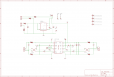
I am wondering if someone look and give their opinion about this circuit for a USB isolator. It can accept external supply to power a USB DAC.
I am skipping the regulator power supply and may be use a Salas reflector to power BUS 2 side.
I am using all "through hole" components. If someone can help with finding alternatives to chokes it will be great.
For now TDK ZJY51R5-2P being considered for digital line instead of ACM4532
and power line will have BOURNS FB20022-4B ferrite beads instead of BLM21.
Since I think 5KV isolation is an overkill for audio board I am planning on using ADUM3160 which is pin to pin compatible and replaced in the circuit without any change in components.
Attachments
Last edited:
Your C2 is quite high. To quote the LT1763 datasheet:
"A maximum value of 0.01µF can be used for reducing output voltage noise to a typical 20µVRMS over a 10Hz to 100kHz bandwidth."
But maybe you don't mind as you are not using the regulator.
"A maximum value of 0.01µF can be used for reducing output voltage noise to a typical 20µVRMS over a 10Hz to 100kHz bandwidth."
But maybe you don't mind as you are not using the regulator.
Using SMD components would be better for this sort of design. Also are the termination resistors required for the speed you'll be using the USB at, especially if you are using PTH components, as they are going to make the layout 10 times bigger than it needs to be (increasing loop areas and possible noise pick up or radiation) never mind trying to control the 90ohms diff pair requirement for USB. PTH is realy the wrong technology for this sort of design, that should be compact.
marce problem is difficult to make a PCB for SMD with inductors.The original inductors are hard to source.
Could you design a PCB that uses alternative inductors and SMD components? They come in all shapes and sizes, SMD included. 11,000 of them at Farnell alone 😉
ere is a nice USB common mode inductor....
http://search.murata.co.jp/Ceramy/image/img/PDF/CHN/L0114S0133DLW21S.pdf
used on a layout with the Adum you are using and a couple of paralleled ADUM6000ARIZ for power isolation.
http://search.murata.co.jp/Ceramy/image/img/PDF/CHN/L0114S0133DLW21S.pdf
used on a layout with the Adum you are using and a couple of paralleled ADUM6000ARIZ for power isolation.
Well I use the full Cadstar set-up, but it costs rather a lot...There are numerous threads in the software section regarding free PCB layout packages, the trouble is its hard to make a decision as everyone has their own views and preferences.
Other than that I have done numerous USB isolated interfaces so any question regarding the layout I may be able to answer....🙂
Other than that I have done numerous USB isolated interfaces so any question regarding the layout I may be able to answer....🙂
I know Eagle is really difficult at first but it's definitely much better than the other free/cheap options. Once you learn how to use it, I think it's actually pretty good.
Not to discourage DIY but have you seen the ADuM4160 based modules available on eBay?
Teralink ADuM4160 USB Isolator board | eBay
Not to discourage DIY but have you seen the ADuM4160 based modules available on eBay?
Teralink ADuM4160 USB Isolator board | eBay
I do see them,but none of them incorporate the ferrite beads and I do not need the regulator part of those boards. Is there anyone who can make a schematic for eagle or a PCB file it would be great.
Last edited:
I presume you want to create a USB isolator with good EMC protection, and good isolation between both sides. Interesting, as I have said I have done a couple of these recently, two that spring to mind are one for some medical equipment and one for some other interesting gear with stringent EMC protection. I may have some ideas that may be of interest. The latter design had to work with protection into the high GHz range...
Still maintain that SMD would be better, size is everything for loops. And a two layer PTH via design would be seriously recommended as a minimum, single sided would be useless for the EMC side as well as the USB signal i8ntegrity.
Still maintain that SMD would be better, size is everything for loops. And a two layer PTH via design would be seriously recommended as a minimum, single sided would be useless for the EMC side as well as the USB signal i8ntegrity.
Thank you Marce,I appreciate your input. It is nearly impossible for me to design a board like that.I wish you could share your idea board with me.
I've got the basics, I'll try and whip together the circuit and board later today.
Thanks a lot Marce, perhaps I can send you a schematic and board file for something similar without ferrite beads in design. Not sure which one to pick for CMC and ferrite. Please check your PM/ email.I am sure you can come up with a better design than the one I have.
May be Wurth is more easy to buy in US Digikey carries their entire WE-SLM series. Seems good.ere is a nice USB common mode inductor....
http://search.murata.co.jp/Ceramy/image/img/PDF/CHN/L0114S0133DLW21S.pdf
used on a layout with the Adum you are using and a couple of paralleled ADUM6000ARIZ for power isolation.
http://www.we-online.com/web/fr/ind...duct_training/Product_Training_CMC_100728.pdf
Last edited:
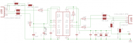
New schematic with updated components
I have an updated schematic with currently available components for a USB isolator. I am wondering if someone will be interested in making a board out of this schematic.
C2-C5 are smd 0.1 uf CERAMIC CAPS.
I have an updated schematic with currently available components for a USB isolator. I am wondering if someone will be interested in making a board out of this schematic.
C2-C5 are smd 0.1 uf CERAMIC CAPS.
Attachments
- Status
- Not open for further replies.
- Home
- Source & Line
- Digital Line Level
- DIY USB isolator