So here is a little thing that I've been working on...
TI makes a USB DAC/ADC with spidf i/o, the PCM2906. They have no evaluation board available, so I've been working up a board.
The chip is basically limited to 16/44, but I'd like to get it going because it has a ADC section, which is great for recording, and spidf i/o, making it capable of attaching other converters right to your computer. Plus it is USB, so you dont have to do any software programing to run it - plug and play. And I already have the parts...
Anyway, I've gotten the board half layed out, but I need some help. I don't know what is required for the spidf i/o section. Looking at other designs, sometimes there are digital 1:1 transformers, sometimes just a 75ohm rca plug, sometimes something labeled 'totx'. So I don't know what to do about the spidf i/o. Also, if you look at the application notes, figure 37 (which I am working off of), IC1 controls the LPF/amp section (Mute and ?). I don't know how to implement these at all. And similarly, I havn't started to cook up the output LPF/amp section.
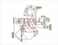
Anyway, my goal is to make something functional and tweak it till I get the best performance, but initally I need to just get it functional. I realize the layout isn't very compact, and perhaps some caps could be closer to the CODEC chip. Any suggestions are appreciated. You will also notice a funny looking footprint for the CODEC - I purposely pulled out alternating SMD pads, so I could reliably solder the chip down. I have doubts I can etch and solder such small traces. Also, the layout picture is just the TOP layer, the bottom has a ground plane, which obscures all the traces and components if I show it. Let me know what you think...
Patrick
here is the link to the PCM2906 datasheet:
http://focus.ti.com/lit/ds/symlink/pcm2906.pdf
TI makes a USB DAC/ADC with spidf i/o, the PCM2906. They have no evaluation board available, so I've been working up a board.
The chip is basically limited to 16/44, but I'd like to get it going because it has a ADC section, which is great for recording, and spidf i/o, making it capable of attaching other converters right to your computer. Plus it is USB, so you dont have to do any software programing to run it - plug and play. And I already have the parts...
Anyway, I've gotten the board half layed out, but I need some help. I don't know what is required for the spidf i/o section. Looking at other designs, sometimes there are digital 1:1 transformers, sometimes just a 75ohm rca plug, sometimes something labeled 'totx'. So I don't know what to do about the spidf i/o. Also, if you look at the application notes, figure 37 (which I am working off of), IC1 controls the LPF/amp section (Mute and ?). I don't know how to implement these at all. And similarly, I havn't started to cook up the output LPF/amp section.
Anyway, my goal is to make something functional and tweak it till I get the best performance, but initally I need to just get it functional. I realize the layout isn't very compact, and perhaps some caps could be closer to the CODEC chip. Any suggestions are appreciated. You will also notice a funny looking footprint for the CODEC - I purposely pulled out alternating SMD pads, so I could reliably solder the chip down. I have doubts I can etch and solder such small traces. Also, the layout picture is just the TOP layer, the bottom has a ground plane, which obscures all the traces and components if I show it. Let me know what you think...
Patrick
here is the link to the PCM2906 datasheet:
http://focus.ti.com/lit/ds/symlink/pcm2906.pdf
Attachments
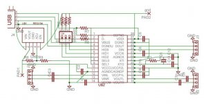
ah yes, I guess I should mention that I want coax spdif out, not optical (totx/torx), and the the jumpers in the layout were meant for rca jack connections, and the two pads were meant as placeholders till I figured out the IC1->output controls.
Ciao.
Ciao.
Hi Cuibono,
I had a very similar project, i based it on the schematics from the pcm2906 specs PDF.
i built a nice board for it but i guess i was not ready yet for soldering this size of chips.
I broke a few of the chips' legs and my heart aswel, im still in mental recovery.
Never the less it still seems like a great project. If you are not very professional in soldering i would advise you to ask someone who is to help you with it.
Gideon
How to set input level with thies chip?
I've built the schematic at the breadboard, and at the 1st time the output level was at 50%, and it is possible to adjust it.
But the input level was too low, and I didn't find any adjustment in WinXP.
I connect inputs to the outputs, and used Spectralab to generate ant to view the signal. In parallel - I've seen the signal in the scope. Output was about 1.8V RMS, but input level was low.
After some switching of/on, the input level goes to maximum, I even not undersooot why! What it can be done?
P.S. I'm also can't find how to move signal from analog input/output to SPDIF ? The ideaa is to make the folowing way to check or DAC or ADC:
SPIF_OUT-> DAC - ADC - SPDIF_IN
Thanks.
After some experimenting with a 2707 i learnt that the spdif output really requires a driver and very possibly a transformer to sound half way decent.
Soldering and etching shouldn't be any problem. Just try a few times when etching. It usually takes a few times to get the process right.
Soldering is quite simple if you know how to (instead of what people might think). Use a solder iron with 10-25 watts with a small point (preferably 1-2mm) and 0,5-1mm solder. Solder pin 1 and the pin on the other side zich is the furthest away from pin 1. This will make sure the IC is stable for the second step. Quickly solder all the pins together. Don't solder any more than 3-5 seconds wich can cause damage to the IC. Then use solder wick to get rid of all the solder between the pins regarding the 3-5 second rule mentioned above. I usually touch the plastic part of the IC after soldering, if it's to hot to touch wait before soldering again. This is usually quite fast & simple, and yet shows a good & clean result.
Soldering is quite simple if you know how to (instead of what people might think). Use a solder iron with 10-25 watts with a small point (preferably 1-2mm) and 0,5-1mm solder. Solder pin 1 and the pin on the other side zich is the furthest away from pin 1. This will make sure the IC is stable for the second step. Quickly solder all the pins together. Don't solder any more than 3-5 seconds wich can cause damage to the IC. Then use solder wick to get rid of all the solder between the pins regarding the 3-5 second rule mentioned above. I usually touch the plastic part of the IC after soldering, if it's to hot to touch wait before soldering again. This is usually quite fast & simple, and yet shows a good & clean result.
- Status
- Not open for further replies.
- Home
- Source & Line
- Digital Source
- Diy Usb Adac