I sure am interested. I have been looking at Koss ES on ebay. Making my own would be impressive, most of all to me.
Hey Setmenu,
Welcome to the forum!
I'd be interested to hear more about your DIY headphones.
Bill
Welcome to the forum!
I'd be interested to hear more about your DIY headphones.
Bill

Well I guess I won't be making a pair of those unless you off er them in kit. Are you working on an amp for them?
Nice pics!!!!
Nice pics!!!!
Hi thatch_ear
The amp is in the pipeline but first things first, MK2 phones/transducers ,still got nasties to sort of the sonic variety!
setmenu
The amp is in the pipeline but first things first, MK2 phones/transducers ,still got nasties to sort of the sonic variety!
setmenu
It seems like you are having a great time. A voyage of discovery without missing takeout food. Maybe you can help me upgrade the transformers and crossovers of my old JansZen mod 60s. They are great but do have some background noise that is self created. Truly if all I listened to was female jazz vocals I would have powerfull tube amps and ES panels. The clarity is outstanding. I have never listened to ES earphones. I am looking forward to it.
Nice work, Setmenu,
Are those stacks of rare earth disk magnets I see under those bolted plates?
How did you accomplish the suspension and why the wavy treatment on the diaphragms? (I suspect there is one answer for both questions...? 🙂)
I haven't seen a magnetic circuit/diaphragm like this before--pretty cool. Did you think of it yourself, or did you adapt something?
What impedence do you get from these?
Thanks for posting it.
Bill
Setmenu...
One word: Awesome!
-Chris
P.S.-Do you have any spectral decay(waterfall) plots and amplitude vs. phase response plots of the phones?
One word: Awesome!
-Chris
P.S.-Do you have any spectral decay(waterfall) plots and amplitude vs. phase response plots of the phones?
Hi Bill
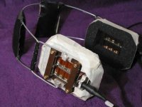
Yes they are stacks of rare earth magnets,the latest version uses
custom flat bar magnets in their place + revised pole pieces to
produce a low profile design with a smaller cavity.
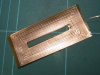
The diaphram is clamped with a bit of silicon rubber sealant at the
frame diaphragm interface to act as terminations/damping.
The wavy form is to control suspension stiffness/resonance.
All the above details are being revised in the next version.
I did think of the design myself but can make no claim as to whether it is unique as such,but have not personaly seen such a layout before.
the units impedence [resistive] at the moment is about 5 OHMs.
The next generation should be above 30 OHM.
Cheers
Setmenu
Yes they are stacks of rare earth magnets,the latest version uses
custom flat bar magnets in their place + revised pole pieces to
produce a low profile design with a smaller cavity.
The diaphram is clamped with a bit of silicon rubber sealant at the
frame diaphragm interface to act as terminations/damping.
The wavy form is to control suspension stiffness/resonance.
All the above details are being revised in the next version.
I did think of the design myself but can make no claim as to whether it is unique as such,but have not personaly seen such a layout before.
the units impedence [resistive] at the moment is about 5 OHMs.
The next generation should be above 30 OHM.
Cheers
Setmenu
Chris
Thanks.
I will be obtaining measuring equipment at some point once I have solved the obvious nasties.
Got to keep a reign on the budget!
Setmenu
Thanks.
I will be obtaining measuring equipment at some point once I have solved the obvious nasties.
Got to keep a reign on the budget!
Setmenu
Setmenu,
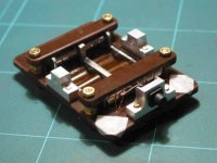
Looking again at your magnetic circuit, I have a few suggestions.
It seems to me that your next revision could use much thicker pole pieces, especially on the ends. (I'm aware that widening the space between the two active halves of your diaphragm to put a thicker pole in the middle could begin to cause uneven treble response.)
I'm pretty sure those thin pole plates are quite saturated where they depart from your magnet stacks. This flux bottleneck means that perhaps only a third of your potential flux is making it onto your pole plates. After the bottleneck, you're projecting the remaining flux from a gap surface of much larger area than the cross section of the pole plate.
In addition to using thicker pole plates, perhaps you could consider reducing the gap surface area (for a corresponding increase in gap flux) by narrowing the pole plates. You'd have to give your diaphragm finer corrugations, but you'd be multiplying the average field density in the gaps. All this would equate to higher sensitivity and let you use even finer VC traces, if you're able to resolve them.
By the way, you may already know this, but common steel today becomes magnetically saturated quite quickly. Pure iron can hold about 2.1 Tesla. Add any carbon, and that number goes down. Add cobalt, and it goes up. Permendure is a 50/50 iron/cobalt alloy that's good for about 2.4 Tesla. Lowther uses it in their PM4. Trouble is, I hear it costs about $1000/Kg.
Sintered neodymium is another excellent flux carrier. Along with your stacks of disk mags, you could use NdFeB magnet bars for your pole pieces. Go to http://www.wondermagnet.com/dev/magnets.html and check out their prices on surplus NdFeB mags--the cheapest I've come across.
Your design is slick and original--I think it has all kinds of possibility!
Bill
Bill
Thanks for your comments.
On pole pieces.
The new version of this design uses a different symetrical profile.
I have tried thicker pole pieces ,not enough difference to warrent
the weight increase.
And yes all three pole pieces will have the same thickness now
[the thicker one].
I agree the magnetic circuit is does not make best use of the
magnets[new version has slightly more mass in the bar magnets]
but this type of transducer is not effiecient in any form really
compared to more conventional moving coil designs.
Infact regarding width of the diaphragm this has increased a couple of mm on the latest model [stronger magnets to compensate] because I feel width up to a point is good as there
is an air gap each side of the diaphragm the greater the ratio
of diaphragm area to gap area will improve pumping at low freguency and reduce the tendancy to twist as air tries to spill over the edge.
[I appologise if I spout BS alot ,I am an artist afterall!]
On the subject of corrugations this is one very critical area
influencing resonance and rattles and ia on the agenda for heavy
research one I have a pile of etchings to fold[and ruin ..hehe].
I feel flatter the better with those corugations as they [if you think about it] want to flatten out with the application of a signal
and this could certainly help develop some lovely sonic nasties .
On magnets as pole pieces.
I would love that! custom shaped neo magnets could be at my
fingertips at reasonable price but for one problem mentioned earlier.
The centre pole piece needs to be a single pole as I cant seem
to find any monopole magnets[they would be strange things eh]
I would have to resort to a sandwich of opposed pole magnets
with a pole piece of suffiecient thickness between them to prevent
repulsion[the basic principle of this circuit] this would result in a
centre piece width of some 9-10mm......not good.
Anyway thanks again for the input,
and the friendly intro to the DIY Forums.🙂
Setmenu
Team flat things😛
- Status
- Not open for further replies.
- Home
- Loudspeakers
- Multi-Way
- DIY transducers--the final frontier