Would like to ask for help. I have a plan to 3D print and build my own amplifier using ZK amplifier boards widely available on Amazon ( e.g. Zk-502A) and would like to pair it with this vintage looking VU meters also available on Amazon. How can I connect the VU board with the amplifier?
Originally I though I would just hook the VU meter board to the amplifier output for speakers but that is not recommended or even not possible if the board is not grounded ( which I do not know how to identify ).
Any help would be appreciative.
I found this post on Amazon but do not know how this applies or could apply to the ZK DIY amplifier boards
It is VERY important that you understand the input to this board is intended to have a standard ground referenced set of signals going to the left and right inputs. This is the case with audio components interconnections, and pre-amplifier outputs that feed INTO power amplifiers. THIS IS NOT so common with amplifier OUTPUTS that feed to speakers. MANY amplifiers have differential outputs that drive both the positive and negative amplifier to speaker connections so all the speaker connections are driven and NOT grounded, and MAY OR MAY NOT be ground referenced even.
WARNING: If you MUST connect this to amplifier speaker outputs, FOLLOW THE NEXT STEPS AS APPROPRIATE FOR YOUR Amplifier CAREFULLY!
Amplifier outputs and connections to this board.
1. - Amplifier with a fully ground referenced output the the speakers, only the positive amplifier output driven. - Connect the Right positive Speaker out from the amplifier to the RIGHT signal input on the board. Connect the LEFT in a similar manner. Connect the common input to either the left or right common (-) ground connection.
2. - Amplifier with a ground referenced bi-polar output, both the positive and negative speaker outputs are driven, in relation to ground, being driven in opposite polarities from each other. - Connect the Right positive Speaker out from the amplifier to the RIGHT signal input on the board. Connect the LEFT in a similar manner. DO NOT connect the common input to a speaker output connection or you will likely destroy your amplifier! Connect the common input to either the grounded common point on your amplifier, this may be hard to determine, you may need assistance of someone familiar with your amplifier, or additional support from the amplifier vendor.
3 - Amplifier with isolated outputs, not referenced to ground in any way. - DO NOT USE THIS CONNECTED TO THE SPEAKER OUTPUT AS DAMAGED WILL LIKELY RESULT.
If I understand this dilemma correctly I would need to find "common ground" on the AMP or confirm if the ( - ) signal is driven or not.
Vendo, the issue is the "bridge mode" output of the amplifier. Neither end of the loudspeaker is connected to ground. This means you can't just wire the VU meter across the speaker leads.If I understand this dilemma correctly I would need to find "common ground" on the AMP or confirm if the ( - ) signal is driven or not.
However, this doesn't have to stop you. Your VU meter will have a ground lead. Look at the power connector on your amplifier board, and find a suitable copper trace connected to the negative of the power jack. That is your ground.
Ground from your VU meter board gets connected to ground on the amplifier board. (Any copper trace connected to the negative pin from the power supply jack.)
Then you can connect the signal input wire of your VU meter to either one end of your loudspeaker output, and it should work - assuming the voltage levels are correct. (If the VU meter wants 100 mV and you feed it 10V from the speaker, you can damage it.)
Before you try this, do you have any more information you can post on the VU meter? Does it require DC power, or is it passive? Does it expect a line-level audio signal, or a speaker-level one? If it requires DC power, how many volts does it want?
If you can give me that information, there will be less chance of damaging anything when connecting it all up.
-Gnobuddy
thank you very much Sir for responding with such a positive newsVendo, the issue is the "bridge mode" output of the amplifier. Neither end of the loudspeaker is connected to ground. This means you can't just wire the VU meter across the speaker leads.
However, this doesn't have to stop you. Your VU meter will have a ground lead. Look at the power connector on your amplifier board, and find a suitable copper trace connected to the negative of the power jack. That is your ground.
Ground from your VU meter board gets connected to ground on the amplifier board. (Any copper trace connected to the negative pin from the power supply jack.)
Then you can connect the signal input wire of your VU meter to either one end of your loudspeaker output, and it should work - assuming the voltage levels are correct. (If the VU meter wants 100 mV and you feed it 10V from the speaker, you can damage it.)
Before you try this, do you have any more information you can post on the VU meter? Does it require DC power, or is it passive? Does it expect a line-level audio signal, or a speaker-level one? If it requires DC power, how many volts does it want?
If you can give me that information, there will be less chance of damaging anything when connecting it all up.
-Gnobuddy
here is the VU Meter board spec
for the AMP I have on hand ZK-TB21 and measured pins in the picture. on the bottom side of the PCA I measured the power in connector pins and they were 12V as per PSU I`m using. Then I measured Speaker termina ( + ) with Power In Ground ( - ) and multimeter was showing 0.9V which is I believe exactly what the VU Meter is expecting.
this is the connection which I beleive you were suggesting and which could work
You're very welcome. I think we can get your VU meters working properly, with a little luck.
Also, was this a digital multimeter (DMM)? (Old-school analogue multimeters measure AC differently than DMMs - they can be confused if they are set to measure AC, but then connected to a DC source.)
I'm asking because it's not clear if you were measuring 0.9V DC, or 0.9V AC.
Either number is surprising. I would expect +6V DC (half of your amplifier supply voltage) at each end of the loudspeaker when there is no signal to the amplifier.
If there is no audio being fed to the amp, the AC voltage at each speaker end should be very, very small (millivolts).
In any case, regardless of what you measured, if you have a 12 volt DC power supply for your amplifier, when the amplifier is driven to full output, each end of the speaker should have something very close to 9 of 10 volts peak-to-peak voltage on it.
Unfortunately, we still don't know if your VU meter board wants 9 volts RMS, 9 volts peak, or 9 volts peak-to-peak. These are three very different things.
1)If your VU meter wants 9V peak-to-peak, you're all set.
2) If your VU meter wants 9V peak (not peak to peak), it will overload on peaks - not good, you don't want those delicate moving-coil mechanisms slamming against their end-stops. (But you may be able to turn down the VU meter sensitivity with those blue trimpots?)
3) If your VU meter wants 9V RMS, it will never reach full scale with your amp powered from 12V DC. This is safe for the meters, but irritating for you.
Can you find any more technical data on your VU meter board? If not, you will have to experiment, carefully, to make sure the meters aren't going to be overdriven.
Do the blue trimpots on your VU meter adjust the meter sensitivity? If so, do you know what the range of adjustment is?
It's frustrating that so many of these electronic boards from Amazon and Ebay come without enough technical information to use them properly. I've had the same issue myself. Hopefully if you search the Internet using key words (Brand and model of your VU meter), you'll find the information we need.
With a bit of luck, the blue trimpots on the VU meter board can be adjusted to get your meters working properly, matching the output voltage from your amplifier, so they hit full just as the amplifier enters clipping.
The most important thing is not to damage the VU meters by driving them too hard - if you start with the amplifier volume at minimum, and turn it up cautiously, you will soon find out if the amplifier clips first, or the VU meters hit their stops first. Don't let them hit their stops hard!
-Gnobuddy
Did you have the multimeter set to read DC voltage, or AC voltage? Was there any signal (audio or sine wave) going into the amplifer when you did this measurement?...I measured Speaker terminal ( + ) with Power In Ground ( - ) and multimeter was showing 0.9V which is I believe exactly what the VU Meter is expecting.
Also, was this a digital multimeter (DMM)? (Old-school analogue multimeters measure AC differently than DMMs - they can be confused if they are set to measure AC, but then connected to a DC source.)
I'm asking because it's not clear if you were measuring 0.9V DC, or 0.9V AC.
Either number is surprising. I would expect +6V DC (half of your amplifier supply voltage) at each end of the loudspeaker when there is no signal to the amplifier.
If there is no audio being fed to the amp, the AC voltage at each speaker end should be very, very small (millivolts).
In any case, regardless of what you measured, if you have a 12 volt DC power supply for your amplifier, when the amplifier is driven to full output, each end of the speaker should have something very close to 9 of 10 volts peak-to-peak voltage on it.
Unfortunately, we still don't know if your VU meter board wants 9 volts RMS, 9 volts peak, or 9 volts peak-to-peak. These are three very different things.
1)If your VU meter wants 9V peak-to-peak, you're all set.
2) If your VU meter wants 9V peak (not peak to peak), it will overload on peaks - not good, you don't want those delicate moving-coil mechanisms slamming against their end-stops. (But you may be able to turn down the VU meter sensitivity with those blue trimpots?)
3) If your VU meter wants 9V RMS, it will never reach full scale with your amp powered from 12V DC. This is safe for the meters, but irritating for you.
Can you find any more technical data on your VU meter board? If not, you will have to experiment, carefully, to make sure the meters aren't going to be overdriven.
Do the blue trimpots on your VU meter adjust the meter sensitivity? If so, do you know what the range of adjustment is?
It's frustrating that so many of these electronic boards from Amazon and Ebay come without enough technical information to use them properly. I've had the same issue myself. Hopefully if you search the Internet using key words (Brand and model of your VU meter), you'll find the information we need.
Yes, exactly as you drew it. Keep in mind the 9V AC supply for the VU meter must be floating relative to the amplifier power supply - in other words, do not ground either end of the 9V AC supply to the amplifier!this is the connection which I beleive you were suggesting and which could work
With a bit of luck, the blue trimpots on the VU meter board can be adjusted to get your meters working properly, matching the output voltage from your amplifier, so they hit full just as the amplifier enters clipping.
The most important thing is not to damage the VU meters by driving them too hard - if you start with the amplifier volume at minimum, and turn it up cautiously, you will soon find out if the amplifier clips first, or the VU meters hit their stops first. Don't let them hit their stops hard!
-Gnobuddy

Thank you Sire, you are giving me enormous lesson here and I`m very grateful for your time. Hopefully this chat can yield some valuable information for other DIYers and inspire them. I have been experimenting with the audio just few weeks back and most of these topics are beyond my knowledge. ( e.g. 12V DC vs AC )
Regarding the measurement.
Regarding the Vu meter board.
- the board does not have name/SKU/model#. It seems it is one of those Chinese mushroom products. But I did search all usual portals ( ebay, aliexpress.. ) and here is what I have found.
Input Voltage
Meter drive board specifications:
Comments from foreign buyers and bad translation
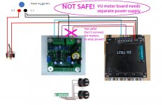
Here is drawing showing how I imagine connecting and wiring these guys in the box. ( The AMP KZ-TB21 has option to power via barrel ( far right ) and wire terminal ( next to the barrel ).)
I`m not sure if this schematic meets your remark "Keep in mind the 9V AC supply for the VU meter must be floating relative to the amplifier power supply - in other words, do not ground either end of the 9V AC supply to the amplifier! " or it implies I need separate power supply for the VU meter board. Originally I though I would use for the board cheap buck convertor and bring down 12V to 9V perhaps I can use that to separate main ground from the Amp ground for the VU meter input power.

Regarding the measurement.
- Did you have the multimeter set to read DC voltage, or AC voltage? Also, was this a digital multimeter (DMM)? I used CRAFTSMAN 3482141 the mini one and I was measuring Vdc set on 20 on the dial.
- Was there any signal (audio or sine wave) going into the amplifier when you did this measurement? Yes, I had the volume set to ~50-60% to the point of being very loud . So the 0.9V was DC signal under load. I will measure +/- directly on the L and R speaker later today and report back. I`m curiouse what power goes to the speakers in general.
Regarding the Vu meter board.
- the board does not have name/SKU/model#. It seems it is one of those Chinese mushroom products. But I did search all usual portals ( ebay, aliexpress.. ) and here is what I have found.
Input Voltage
- The pictures mention AC9V , AC 9V-20V (500mA)
- The posting spec mentions
- Working voltage: 6 ~ 12V AC or DC. The main picture is the DC 9V lighting effect. (AC: 10.6V, current 48mA)."
- UV level meter specifications:DC500μA , VU meter head with backlight, Meter DC internal resistance: 630 ohms. White dial, yellow backlight, standard VU indicator, The backlight is an incandescent light bulb. Working voltage: 6 ~ 12V AC or DC. The main picture is the DC 9V lighting effect. (AC: 10.6V, current 48mA).
- Vu Meters are powered from the board so this is a bit contradicting information unless the board converts maximum mentioned input current to 12V DC which is unlikely.
Meter drive board specifications:
- Supply voltage AC 9V 500mA (9V-20V)
- Size: 51mmX51mmX25mm
Comments from foreign buyers and bad translation
- " So which power supply is needed, stable or not? A: You can constant and change, no difference works from both. "
- " How many volts on the input can be given on the board, written 9-20, I have a 12 v volley electrolytic condensator A: I connected 12, everything is fine "
Here is drawing showing how I imagine connecting and wiring these guys in the box. ( The AMP KZ-TB21 has option to power via barrel ( far right ) and wire terminal ( next to the barrel ).)
I`m not sure if this schematic meets your remark "Keep in mind the 9V AC supply for the VU meter must be floating relative to the amplifier power supply - in other words, do not ground either end of the 9V AC supply to the amplifier! " or it implies I need separate power supply for the VU meter board. Originally I though I would use for the board cheap buck convertor and bring down 12V to 9V perhaps I can use that to separate main ground from the Amp ground for the VU meter input power.
Last edited:
If you wire it like shown in the last post, it should work.
A look at the PCB for the VU meters shows two pairs of capacitors, which should separate DC voltage from the needed AC signal ( input voltage from the amp and output voltage to the meters both contain a DC voltage).
Do not connect the loudspeaker negative (-) to any ground point or you will fry your installation.
The two blue adjustable resistors then have to be adjusted in a way that the meters show some movement you like. Start with a low volume and of music.
The correct way of adjusting the VU meter would be a known 1000 Hz rms signal on the amps input, set in a sensefull relation to the amps gain.
Here's a simple explanation: https://byjus.com/physics/difference-between-ac-and-dc/beyond my knowledge. ( e.g. 12V DC vs AC )
For our purposes:
1) The 12V that powers your amplifier is DC.
2) The audio signal you are feeding into your amplifier is AC. (Our ears hear tiny changes in air pressure, which we call sound. Those tiny pressure changes are turned into fluctuating current (AC) to make an audio signal.
3) The voltage at one end of the speaker is pure DC when no signal is fed to the amplifier. But if you feed audio to the amplifier, then the voltage at one end of the speaker is a mixture of AC and DC.
This last point may confuse your DMM.
If you want to measure DC at the speaker, keep the volume at zero, power up the amp, set the DMM to DC volts, and measure from one end of the speaker (either end) to power ground. You should read something close to 6 volts DC (when the amp is powered by 12 V).
Okay. I've bought things like that, too. The price is nice, but sometimes the lack of technical information is frustrating.- the board does not have name/SKU/model#. It seems it is one of those Chinese mushroom products.
That may mean that the blue trimpots will let you adjust the amount of signal needed (to drive the VU meter to full deflection) anywhere between 9V and 20V.Input Voltage
- The pictures mention AC9V , AC 9V-20V (500mA)
We still don't know if this is 9V RMS, 9V peak, or 9V peak-to-peak. But the good news is that I made one mistake yesterday.
1) If the board expects 9V peak-to-peak, you're golden. You may need to fine-tune the blue trimpots a little.
2) If the board expects 9V peak, then you won't ever get full meter deflection, but the meter won't be damaged (this was my mistake - I said the opposite in my previous post, i.e., that the meter would deflect too far. I was wrong).
3) If the meter expects 9V RMS, you also won't ever get full meter deflection (but the meters won't be damaged).
So it's mostly good news - at least the meters won't be overdriven.
This is not safe - please don't connect the boards in this way.Here is drawing showing how I imagine connecting and wiring these guys in the box.
Your VU meter board is designed for 9V AC power. But the electronics on the board needs DC power. The VU meter board has a set of diodes (small black cylinder) onboard, which can convert AC to DC.
Even though the VU meter board was designed to be powered from AC, it will work if you power it from 12V DC. Unfortunately, this has a side effect. If you feed 12 V DC to the VU meter board, because of the diodes on the board, the ground of the VU meter board will not be at the same voltage as ground from the power supply.
That means you cannot safely power the VU meter from the same 12V DC power supply as your amplifier.
In short, you must use a separate 12VDC or 9V AC power supply for the VU meter board.
That's right, you have to use a separate power supply for the VU meter board. Either 9V AC (from an old-fashioned 60 Hz iron transformer), or 12V DC (from a modern wall-wart switch mode power supply.)... or it implies I need separate power supply for the VU meter board.
I've made some notes on the image you posted, to show you the dangerous connections.
-Gnobuddy
Attachments
Turbowatch2, did you notice the bridge rectifier (small black cylinder) on the VU meter board?If you wire it like shown in the last post, it should work.
This is designed to turn 9V AC input power into DC power for the board. It has the side effect that the DC ground of the VU meter board is not at the same voltage as either of the input power wires.
So no, it is NOT safe to wire the VU meter board as Vendo suggested in post #8.
-Gnobuddy
Thank you both @Gnobuddy and @Turbowatch2 for your evaluation. More eyes know more.
Second power supply is doable but it is inconveniece. There are devices such as Aiyima T9 with the same VU meter working along with amplifier out of single power supply. Their logic board is probably next level than this.
What would you say if I insert a buck converter LM2596 between main power barrel and the VU meter board separating the AMP and Meter ground? Would that work?
Attachments
Last edited:
Yes, I agree. This is the unfortunate consequence of the VU meter board being designed to run on AC, and having an onboard bridge rectifier.Second power supply is doable but it is inconveniece.
That VU meter could simply have been powered by DC, and then the entire headache would have gone away. In that case, your original wiring diagram (post #8) would have worked just fine.
This will only work if you can find a DC-DC converter with a fully floating output. That means that neither the ground connection, nor the power connection, goes straight through the converter.What would you say if I insert a buck converter LM2596 between main power barrel and the VU meter board separating the AMP and Meter ground? Would that work?
In a converter like this, your DMM (set to measure resistance) would show open-circuit between the grounds on the input and output sides of the switcher board. No electrical connection at all between the grounds.
Unfortunately, this usually isn't the case. Most of these little buck converters have a common ground for both input power, and output power. A DMM will show near-zero resistance between the input ground and the output ground of these types of switcher/buck converters.
A converter of this type (common input and output ground) will not solve your problem - you will fry things if you do this. 🙁
If you look at the PDF of the LM2596, you can see that both the 12V input and the 5V output all share the same ground. This will NOT work for you. 🙁
-Gnobuddy
thank you @Gnobuddy , your recommendation proved to be the correct one when I checked other available board on Amazon.
I quess the only way to set AMP and VU Meters into one box would be with 2 separate power supplies. But it is still awesome news! I can continue with my project. Good news is that the VU power supply does not have to be high Amp unit, so it will be relatively small box.
I will try to measure resistance when I get home on the buck converter. ( just to confirm your point 🙂
Last edited:
thank you @Gnobuddy , your recommendation proved to be the correct one when I checked other available board on Amazon.
Thats the only simple way. 🙂I quess the only way to set AMP and VU Meters into one box would be with 2 separate power supplies.
(I could probably hack the actual PCB of the VU meter board, and make it work; but I wouldn't recommend that you try that. A mistake would cost too much. Better to just get a cheap second power supply, if you don't already have something suitable lying around your house.)
I used to shop for power supplies at the local Value Village (a thrift-store chain in Canada). I often found small power supplies there for $4 or less. All you need is any 12V DC power supply that can supply enough current for the VU meter board.
-Gnobuddy
Thats the only simple way. 🙂
(I could probably hack the actual PCB of the VU meter board, and make it work; but I wouldn't recommend that you try that. A mistake would cost too much. Better to just get a cheap second power supply, if you don't already have something suitable lying around your house.)
I used to shop for power supplies at the local Value Village (a thrift-store chain in Canada). I often found small power supplies there for $4 or less. All you need is any 12V DC power supply that can supply enough current for the VU meter board.
-Gnobuddy
local Arc thrift store here in Colorado is my source of power supplies as well. Sometime you can find a nice high amp one for cheap.
it was pleasure @Gnobuddy , I will post result once I finish the 3D printed box.
Attachments
Looks good to me!final diagram
Looking forward to your report. I hope all goes well.
-Gnobuddy
You may use a separate PS, but it should work from the amps supply as well. The rectifier does not do any harm, it just leads to a voltage drop of .7 volt in the DC rectified a second time..
As you have to connect the ground at the "speaker in" on the VU board as well, you will have the same ground level as the amp anyway. Just measure the resistance if you like. There will be no current flow that can do any harm to that circuit.
The negative (-) out of the bridge rectifier will be at amp negative out as well. You may see two different ground levels if you want, but this is no problem. One ground is "a little more ground" than the other to say it simple, but relevant is only the main ground. If you want, do not connect amp ground at the VU board "AC in" at all, should work with positive only. I just did not want to confuse you.
The VU board has some IC feed by a voltage set by the regulator on board. It should work up to 30V DC. The suggested 20V AC from the instruction give around 28V DC. So no prolem there. You only get into trouble if your amp runs on more than 30V. That is when the second power supply is needed.
These Chinese boards are build for idiots, so they try to make anything fool proof.
For example, if you look at your amp board, you will see two diodes at the positive (+) in for the supply. These are not needed and degrade amp performance. They are just there to protect the seller of the board from claims when the idiot who buys it, does not know what (+) and (-) and AC and DC are. These PCB's are sold all over the world and usualy used by people without formal education in electronics.
- Home
- Amplifiers
- Class D
- DIY TPA3116 amplifier with VU meters. How to connect?