Using the same clocks feeding a tda1541a. So it's working.And its running without problems ? I thought all the time, that the TDA1541A needs the 22/24Mhz clocks...
Ad.
And its running without problems ? I thought all the time, that the TDA1541A needs the 22/24Mhz clocks...
As with the cathode resistors lately. If you don’t believe it, why don’t you give it a try yourself?
As with the cathode resistors lately. If you don’t believe it, why don’t you give it a try yourself?
I would try, but my reclocker came with 22/24Mhz. Was just wondering, because i read many times, that you need the 22/24 clocks, but very cool, that its not the case. Never wanted to say it will not run, I‘m here to learn.
Thanks to the manual by Greg, i was able to power up the board and check voltages, they were within 0.25v of the spec.
As i am waiting for C6, C14 and C20 to be delivered, can we use - CGA6P1X7R1E106K250AC in these three locations ?
Yes, Sonics would not match to the 22uf Rubycon, but would it be fine for using till the caps arrive ?
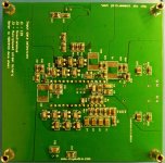
Also attached is the pic of the board.
Thanks
Harsha
As i am waiting for C6, C14 and C20 to be delivered, can we use - CGA6P1X7R1E106K250AC in these three locations ?
Yes, Sonics would not match to the 22uf Rubycon, but would it be fine for using till the caps arrive ?
Also attached is the pic of the board.
Thanks
Harsha
Attachments
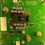
Thanks to the manual by Greg, i was able to power up the board and check voltages, they were within 0.25v of the spec.
As i am waiting for C6, C14 and C20 to be delivered, can we use - CGA6P1X7R1E106K250AC in these three locations ?
Yes, Sonics would not match to the 22uf Rubycon, but would it be fine for using till the caps arrive ?
Also attached is the pic of the board.
Thanks
Harsha
Hi Harsha,
You can use the D3 without C6, C14 and C20 installed, it will work without them but the output impedance in the bass region will be around 14 mohms instead of around 3 mohms - I would leave the pads clean until you get the correct caps.
.25V seems a little far out of spec, did you have a dummy load while testing?
Hi Ryan,
Thanks for the response, Some more details, which may be essential.
Voltages were measured with only the bare minimum components as specified in the Guide (X1, X2, X3, C5, C13, C21, R19, R20, R18, R24, R23, R25, R28, R30, R27, R29, R21, R17,R16, Q3, Q2, Q1, CC1, V1, R22.)
Load resistors were added as per the Guide and voltage across them were measured.
I will again measure the voltages now, as there are all components soldered.
Regarding caps, I will proceed as suggested by you.
Thanks
Harsha
Voltages were measured with only the bare minimum components
Ok, that makes sense now.
Hi,
What is the highest samplerate you have got with this design? I guess with simultaneous it is possible to go to 192khz?
Regards,
Eagerly waiting until the boards arrive 😉
What is the highest samplerate you have got with this design? I guess with simultaneous it is possible to go to 192khz?
Regards,
Eagerly waiting until the boards arrive 😉
Hi,
What is the highest samplerate you have got with this design? I guess with simultaneous it is possible to go to 192khz?
Regards,
Eagerly waiting until the boards arrive 😉
Hi Supersurfer,
I've tested up to 176k.
https://www.diyaudio.com/forums/group-buys/326972-diy-i2s-simultaneous-converter-pcb-12.html#post6421299
Thanks Ryan,
Than it would be possible to go to 192khz with 24mhz clocks. In I2S the TDA1541 will not go higher than 88,2-96khz and I assumed that the simultaneous connection would allow the double sample rate.
I have build the new Driscoll clock units from Andrea that I will use, together with the 50hz Dem I reckon it will be a very low jitter performance.
Regards,
Thanks Ryan,
Than it would be possible to go to 192khz with 24mhz clocks. In I2S the TDA1541 will not go higher than 88,2-96khz and I assumed that the simultaneous connection would allow the double sample rate.
I have build the new Driscoll clock units from Andrea that I will use, together with the 50hz Dem I reckon it will be a very low jitter performance.
Regards,
Hi Supersurfer,
Ill look forward to hearing your impression with Andreas Driscoll clock!
Yes the 50hz DEM, along with the digital attenuators, and simultaneous mode input all help to minimize added jitter inside the chip. And with a very low phase noise clock, its sure to sound great.
Last edited:
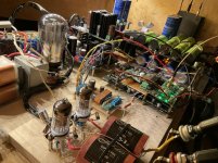
I have also planned to make the differential dac; canceling out the common mode noise and the added output current would also benefit significantly I guess.
I have good experience with the dddac in full balanced mode and would like to hear how this ads to the TDA sound.
Currently I have the TDA dac running on a perf board in I2S with the 5,6mhz driscoll and it is very promising!
I have good experience with the dddac in full balanced mode and would like to hear how this ads to the TDA sound.
Currently I have the TDA dac running on a perf board in I2S with the 5,6mhz driscoll and it is very promising!
Attachments
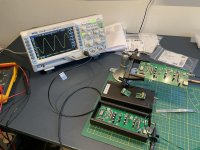
Very nice, thanks for sharing the photos - some nice gear there. Can you share any info on the differential output stage you plan on using?
Thanks.
I have no plans for a differential output stage yet. I will first try with iv resistor only as my tube amplifiers use a volume transformer that is connected floating on the primary side, so it can be loaded with a differential signal (This is working very good with the dddac) it is nice that you have implemented the dc nulling functionality for driving transformers. I have a lot of gain in my system so it may be enough.
But if that does not work a differential pre amp tube stage would be a possibility. I can design a nice one with some tubes and maybe an output transformer.
Regards,
Thanks Ryan,
...In I2S the TDA1541 will not go higher than 88,2-96khz and I assumed that the simultaneous connection would allow the double sample rate...
Hi,
I'm not sure if it helps, but perhaps. The JLSounds I2SoverUSB Interface has something mentioned about I2S at 192khz with external MCLK.
Here is what they write :
"TDA1541 in I2S mode in 32-bit frame with external MCLK."
Pin27 of the TDA1541 must be connected to +5V, pin2 of TDA1541 and pin4 of TDA1541 must be tied together. The DAC is working up to 192kHz in this mode.
Perhaps it helps, dont know.
Hi Linuxgeek,
Thank you for your reply. I already have the dac connected in this way but it will not go higher than 96khz (with 49mhz clocks) when fed by a fifopi. Maybe the fifopi is the limiting factor.
Thank you for your reply. I already have the dac connected in this way but it will not go higher than 96khz (with 49mhz clocks) when fed by a fifopi. Maybe the fifopi is the limiting factor.
Hi Linuxgeek,
Thank you for your reply. I already have the dac connected in this way but it will not go higher than 96khz (with 49mhz clocks) when fed by a fifopi. Maybe the fifopi is the limiting factor.
Hi,
perhaps its really the clocks. Im using 22/24Mhz on my reclocker and 192khz does run.
I habe seen a copper foil on your DAC IC. Is this a temperature thing or shielding ?
Last edited:
....canceling out the common mode noise and the added output current would also benefit significantly I guess.
One other thing is the canceling of some even order harmonics - as a result the sound is cleaner and has less "bloom" - especially in the midrange, which may or may not be desirable.
Another effect is bit averaging - I remember EC talking about this. This could also have contributed to the more accurate/less bloomy sound.
Hi,
perhaps its really the clocks. Im using 22/24Mhz on my reclocker and 192khz does run.
I habe seen a copper foil on your DAC IC. Is this a temperature thing or shielding ?
Hi,
I use 5-6, 11-12, 22-24, 45-49mhz clocks and none of them play 192khz files on the tda1541a. On the pcm1794 (dddac, nos mode) it playes 192khz with 24mhz and higher clocks.
Are you using a fifopi or something else?
The copper foil was an experimental shield, I took it off because I did not notice an effect.
I dont have Fifopi, Im using a modified Allo Kali.
- Home
- Group Buys
- DIY TDA1541A PCB "D3"