Anyone familiar with the new Synergy Amps modular system? its based on the old Randall MST modules.
I want to see if I can build my own modules and was hoping that someone could give me a nudge in the right direction.
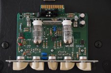
I assume the connector on the back is to supply power to my pre-amp module, take signal in and out and switch between channels. If anyone has built their own module the pin out and some general advice would be much appreciated.
I want to see if I can build my own modules and was hoping that someone could give me a nudge in the right direction.
I assume the connector on the back is to supply power to my pre-amp module, take signal in and out and switch between channels. If anyone has built their own module the pin out and some general advice would be much appreciated.
Attachments
Ok, so here is step one of my design.
I created a template that you can hook up to any pre-amp and you should be good.
It looks like the MTS modules use three optocouplers, two connected to an NPN transistor which allows input and output signal to flow once pin7 receives power and one connected to a PNP transistor that seems to disable the module when pin7 is off (connected to ground) this second optocoupler seems to be connected between the first and the second gain stage on most schematics and pulls the signal down to ground when pin7 is off.
This looks pretty simple but it far from the final design. First of all, it only allows me to either enable er bypass a single channel. As I understand it pin8 is used in conjunction with pin7 to switch between channels. Synergy units also have circuitry That detects how the tubes are biased.
Here is my Schematic for the optocouplers.
Here is another image that shows how they are being used.
I created a template that you can hook up to any pre-amp and you should be good.
It looks like the MTS modules use three optocouplers, two connected to an NPN transistor which allows input and output signal to flow once pin7 receives power and one connected to a PNP transistor that seems to disable the module when pin7 is off (connected to ground) this second optocoupler seems to be connected between the first and the second gain stage on most schematics and pulls the signal down to ground when pin7 is off.
This looks pretty simple but it far from the final design. First of all, it only allows me to either enable er bypass a single channel. As I understand it pin8 is used in conjunction with pin7 to switch between channels. Synergy units also have circuitry That detects how the tubes are biased.
Here is my Schematic for the optocouplers.
An externally hosted image should be here but it was not working when we last tested it.
Here is another image that shows how they are being used.
An externally hosted image should be here but it was not working when we last tested it.
- Status
- Not open for further replies.