Matttcattt said:how did you drill the holes in the correct places? did you use a template? if so, how did you make it?
I usually make the holes (both for drivers and ports) using a router and jigs. For smaller holes I use the one from PartsExpress (Jasper Jig). For larger holes like the one for 8" driver, I use what I made.
Matttcattt said:i meant in the aluminium for the amplifier 🙂
I don't think you asked the holes for OPA549 because it's simply making a 6-32 hole/thread.
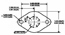
As for the OPA541AM in TO-3 package, yes, I used a sort of template. I downloaded the datasheet from TI, copied the mechanical drawing of the chip, pasted it into a graphics software and resized it the exact size of the amp. Then, I punched the location of holes using the printout as a template. And then, drilled holes. I drilled two larger holes for mounting the chip the the aluminum plate. Attached is the mechanical drawing of OPA541AM.
Attachments
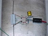
And this is a prototype amplifier on a 0.25"-thick aluminum plate. 🙂
I used an inverting amplifier configuration with 2.2uF input cap, 22k at inverting input, 220k for feedback, 22k (or 15k, not sure) with 0.1 uF btwn non-inverting input to ground.
I'm not really sure if this is good as a subwoofer amplifier. It would be great if anybody could give me some advice.
I used an inverting amplifier configuration with 2.2uF input cap, 22k at inverting input, 220k for feedback, 22k (or 15k, not sure) with 0.1 uF btwn non-inverting input to ground.
I'm not really sure if this is good as a subwoofer amplifier. It would be great if anybody could give me some advice.
Attachments
- Status
- Not open for further replies.