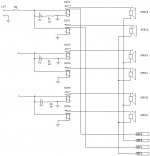
Attached is a diagram of DIY speaker selector that I'm thinking to make before the end of this year. Though only 3 pairs of speakers are drwan in the diagram right now, it will actually be 7 pairs of speakers. So far, it's a simple relay circuit. Any kind of comment would be appreciated. Thanks.
Attachments
parts list
The following is parts list:
Relay:
Miniature enclosed power relay. 12 Vdc, 416 Ohm coil. Pc Pins.SPDT contacts rated 12 Amps @ 277 Vac, 16 Amps @ 250 Vac.
7 Position Rotary Switch:
Miniature single-pole, 7-position rotary switch with 1/8" diameter x 0.22" long shaft. 0.25" diameter 0.27" long threaded bushing. 0.6" diameter x 0.68" long body. Gold-plated solder terminals.
Power supply:
Input: 115 / 230 VacOutputs: 5 Vdc @ 0.7A and 12 Vdc @ 1.3A6.75" x 3.75" x 1.1." 9" wire leads with Molex-type connectors for output. 115/230 V selector slide switch.
These are pretty much I can think of now. Please feel free to add comment. Thanks.
The following is parts list:
Relay:
Miniature enclosed power relay. 12 Vdc, 416 Ohm coil. Pc Pins.SPDT contacts rated 12 Amps @ 277 Vac, 16 Amps @ 250 Vac.
An externally hosted image should be here but it was not working when we last tested it.
7 Position Rotary Switch:
Miniature single-pole, 7-position rotary switch with 1/8" diameter x 0.22" long shaft. 0.25" diameter 0.27" long threaded bushing. 0.6" diameter x 0.68" long body. Gold-plated solder terminals.
An externally hosted image should be here but it was not working when we last tested it.
Power supply:
Input: 115 / 230 VacOutputs: 5 Vdc @ 0.7A and 12 Vdc @ 1.3A6.75" x 3.75" x 1.1." 9" wire leads with Molex-type connectors for output. 115/230 V selector slide switch.
An externally hosted image should be here but it was not working when we last tested it.
These are pretty much I can think of now. Please feel free to add comment. Thanks.
SPEAKER SELECTOR CIRCUIT
It looks like your circuit is what's called "break before make". To cut to the chase, using this circuit will blow out your amplifier. Going from seeing infinite impedance to almost nothing will cause a feedback spike that causes the output stage to turn on to damaging levels. Its the same thing as if you shorted the output.
I hope you read this before you try it
-Joe E. Baby
It looks like your circuit is what's called "break before make". To cut to the chase, using this circuit will blow out your amplifier. Going from seeing infinite impedance to almost nothing will cause a feedback spike that causes the output stage to turn on to damaging levels. Its the same thing as if you shorted the output.
I hope you read this before you try it

-Joe E. Baby
Well... I haven't noticed that there was a reply. Fortunately, I haven't tried this project. Well... It would be correct to say that I haven't finished the whole project. Everything was assembled on PCBs, but not as a whole.
So, how could I avoid/reduce the feedback spikes? Does this also happen in solid state amplifiers? Could anybody let me know? Thanks.
So, how could I avoid/reduce the feedback spikes? Does this also happen in solid state amplifiers? Could anybody let me know? Thanks.
Re: SPEAKER SELECTOR CIRCUIT
isn't this the way all relay based delay circuits in solid state amps work
greetz Rudy
redrumjoe666 said:It looks like your circuit is what's called "break before make". To cut to the chase, using this circuit will blow out your amplifier. Going from seeing infinite impedance to almost nothing will cause a feedback spike that causes the output stage to turn on to damaging levels. Its the same thing as if you shorted the output.
I hope you read this before you try it
-Joe E. Baby
isn't this the way all relay based delay circuits in solid state amps work
greetz Rudy
Old thread but something of what I need to build also. Pretty much every solid state amp I have has a speaker selector switch that disconnects the speakers completely. Plus there is the power on relay also. There is no dummy load switched in. I looked at the schematics.
It would be also cool to have a multi amp switch also. to switch in different power amps....
It would be also cool to have a multi amp switch also. to switch in different power amps....
As a general rule, solid-state amps don't like a short circuit, and valve amps don't like an open circuit. Each is reasonably happy with the opposite, at least for a while. Therefore a speaker switch for SS should be break before make, and for a valve amp should be make before break. Better still, don't do live switching at all.
- Status
- This old topic is closed. If you want to reopen this topic, contact a moderator using the "Report Post" button.
- Home
- Design & Build
- Parts
- DIY speaker selector
