Maybe I am confusing myself, but my goal is to have these LCR to play in conjunction with a seperate sub and I am hoping to have useable range of 80 hz and above, meaning no more than 3dB down at 80hz. Using Winspeakerz I am having a hard time meeting the minimum recommended vent (port) volume) which I am assuming if I do not meet, will introduce the potential of "chuffing", or other port noise.
At an 80Hz tuned point, Winspeakerz indicates a pair of 1.5inch ports 4 inches (3.984") will have only 3.5 square inches of vent area, the minimum req. is 4.12... now assuming I am not getting into the weeds, between computer simulated best sound, and what will actually be real world results, based on the minimum vent area I'd need at least to tune the box down to 68 Hz using the 1.5inch port to have enough vent area to meet the req. size. (my prefabs are only 4"), this frequency requires a 6 inch... however moving to a larger port, say 2" seems to solve the problem of not having enough vent area for my sized box, but only if I use a pair of 2" ports which kills my design of a compact LCR speaker by having to mack room for a 2" port.... maybe a sloted port is the way to go, while not as cosmetically apealing.
Another concern in my modeling is the -6db baffle defraction loss the Winspeakerz is simulating on these drivers. Guess it's time to work on a compensation network.....
pblossom said:Greiner, some years ago, showed that locating the port as close as possible to the woofer improved performance of the system. I looked through some of my AES reprints and copies but didn't find the specific article.
I believe this is called mutual coupling, and it is a small effect in most situations. Room placement is more of an effect, as is port compression with typical ports.... As far as placement goes, I wouldn't worry about it much, unless your speaker is very long like a pipe. You would be amazed at how much bass a sealed speaker with an honest 50Hz F3 puts out. If it is home theater, that is a worthy goal as long as you have subwoofer, then you don't need a port in your L-C-R speakers at all 😉
For diffraction concerns, look to the FRD Consortium, or Svante's Edge software. With these you can actually model the diffraction effect. Rule of thumb says you shouldn't correct more than ~3dB of it in a typical listening room.
I don't port my main speakers because the lower roll off of the mains when closed box integrate better to the use of multiple subs. I would never do a room anymore without multiple subs so there is no point in having a ported enclosure at all. Granted a ported enclosure does get a few more Hz at the low end, but with multiple subs this is not an important factor.
I do use ports but only in a bandpass configuration where they act to acoustically LP the drivers response, thus lowering any HF signals that can be localized. But this front porting is quit different than rear porting in that it creates a full monopole not a partial mono/dipole. The dipole response below cutoff is not a good thing. I find an all monopole room system at LFs to work best.
But lets not dwell on dipole/monpole bass and which is better. The room, the number of subs and their location is what matters, not the type of the subs.
Hi,
Midrange output of ports can be a problem - exacerbated by
the natural pipe frequencies of the port length, though it can
be reduced by internal speaker details, still generally rear
ports are less likely to be problematic.
Careful design helps, as does of course port output measurements.
🙂/sreten.
From the first bookshelf speaker I clicked on at stereophile.com :
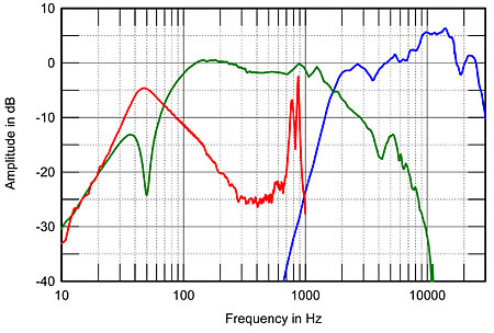
Polk RTi A1 with a small front mounted port - not good (red trace).
Midrange output of ports can be a problem - exacerbated by
the natural pipe frequencies of the port length, though it can
be reduced by internal speaker details, still generally rear
ports are less likely to be problematic.
Careful design helps, as does of course port output measurements.
🙂/sreten.
From the first bookshelf speaker I clicked on at stereophile.com :
Polk RTi A1 with a small front mounted port - not good (red trace).
Lets be clear - its certainly possible to make a system with ports that have a problem. But its just as reasonable to do one that does not have chuffing or HF content. The curve that you show is a "worst case" as I have never seen anything that bad before. There must not be any damping in that system at all. I also suspect that this was done nearfield on the port which is meaningless since the nearfield data at those frequencies won't be right. It does "appear" that the axial response is affected by this port resonance, but thats not certain.
gedlee said:The curve that you show is a "worst case" as I have never seen
anything that bad before. There must not be any damping in that
system at all. I also suspect that this was done nearfield on the port
which is meaningless since the nearfield data at those frequencies
won't be right. It does "appear" that the axial response is affected
by this port resonance, but thats not certain.
Hi,
It is certainly not "worst case", it is the first compact bookshelf in
stereophile.com's review listings with a front mounted port that
I found, It is to a degree a random case, I've seen worse.
The measurements are nearfield (in fact red is summed front and rear
ports) but the 800/900Hz problem is with the front port. You do not
need accuracy in this level to see the problem. The problem is also
illustrated by impedance "wiggles" at the same frequencies.
It is a common issue in commercial speakers and less likely to
be a problem in said speakers if the ports are rear mounted.
🙂/sreten.
sreten said:
Hi,
It is certainly not "worst case", it is the first compact bookshelf in
stereophile.com's review listings with a front mounted port that
I found, It is to a degree a random case, I've seen worse.
The measurements are nearfield (in fact red is summed front and rear
ports) but the 800/900Hz problem is with the front port. You do not
need accuracy in this level to see the problem. The problem is also
illustrated by impedance "wiggles" at the same frequencies.
It is a common issue in commercial speakers and less likely to
be a problem in said speakers if the ports are rear mounted.
🙂/sreten.
A nearfield measurement of the port at 800-900 Hz is totally incorrect and cannot be simply summed back into the woofers measurement. If thats what was done then the whole thing is bogus.
gedlee said:
A nearfield measurement of the port at 800-900 Hz is totally incorrect
and cannot be simply summed back into the woofers measurement.
If thats what was done then the whole thing is bogus.
Hi,
What is bogus is saying it is meaningless.
The phenomena is there and it showed up in the impedance trace.
🙂/sreten.
I think there's a communication problem here.
Both Earl and Sreten both are smart guys, both know the significance of HF pipe modes from the port. Both see that as a bad thing.
What Earl is saying is nearfield measurements of the port don't show the effects of summing with the woofer. At 900Hz, you have both the pipe mode from the port and the midwoofer midrange interaction, making a complex sound field.
Wayne
Its true that we both see it as a bad thing, but I am saying that the attached data file doesn't prove anything because its a nearfield measurement which will show a much higher HF output than would be radiated into the far field. Its not a valid measurement at those frequencies. You need to do far field measurements at these frequencies and that isn't shown. Sure there are port resonances, but a far field measurement would show that they are no where near as significant as the above plot shows.
Its true that we both see it as a bad thing, but I am saying that the attached data file doesn't prove anything because its a nearfield measurement which will show a much higher HF output than would be radiated into the far field. Its not a valid measurement at those frequencies. You need to do far field measurements at these frequencies and that isn't shown. Sure there are port resonances, but a far field measurement would show that they are no where near as significant as the above plot shows.
I recently started a new speaker project, and because I hadn't done a BR for some time, I decided to build a test cabinet that allowed me to assess different port positions. My final cabinet design is a little too time consuming to simply "knock one up", so I just built a simple rectangular box which allowed for 1 or 2 ports to be located in any one of 12 positions around the cabinet. I then cut 3 different port lengths to allow for slightly different cabinet tuning.
Each port position was listened to and also measured in the far-field. Two things became clear by the end of this test.
1. A lower than "optimum" tuning frequency with a roll-off that was somewhere between a BR and a sealed box was preferred.
2. A front positioned port close to the floor gave the most even response.
The bass cabinet was approximately 95 litres and the position of the bass driver meant the port was both close to the floor and the driver. I tried as many combinations as I could, including two ports in different locations, such as one each side of the cabinet, but the front location with either one large port or two closely positioned ports was still preferred. My room is about 16'x13' and the speakers sit just out from the corners along the short wall.
Obviously these are just my findings in my room, but when I saw this thread I thought it might provide some additional information.
Steve
gedlee said:Wayne
Its true that we both see it as a bad thing, but I am saying that the
attached data file doesn't prove anything because its a nearfield
measurement which will show a much higher HF output than would
be radiated into the far field. Its not a valid measurement at those
frequencies. You need to do far field measurements at these
frequencies and that isn't shown. Sure there are port resonances,
but a far field measurement would show that they are no where
near as significant as the above plot shows.
Hi,
Your making assumptions right left and centre.
The port output is normalised by multiplying by its radiating area
to give accurate results at low frequencies for farfield. For a small
radiating port ~ 1" in diameter this will hold up to past 3kHz.
Baffle step is not taken into account, but that is a stereophile
choice, covered by Paul Messengers series of measurement
articles, which outline the methodologies and issues.
Not totally correct is not the same as totally incorrect or bogus.
Much more correct than usual is a more apt description of the plots.
🙂/sreten.
Sort of vented (40Hz) but much worse - pseudotransmission line :
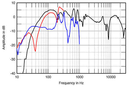
Fig.3 Meadowlark Swift, anechoic response on tweeter axis at 50",
averaged across 30 degrees horizontal window and corrected for
microphone response, with nearfield responses of the woofer (red)
and port (blue) and their complex sum, taking into account acoustic
phase and distance from the nominal farfield point (black), plotted
below 300Hz, 1kHz, and 400Hz, respectively.
I think we're all saying the same thing here. I always look for standing wave modes from port or cabinet, and I usually use Martin King's spreadsheets, as I said earlier. It's a great tool for that. I also sometimes use insulation spanning the cabinet's cross-section. That helps damp higher frequencies inside the cabinet. But the end result is what matters, how the speaker measures in the listening space.
So, since there are indeed some nasty resonances possible, let's talk a little bit about how to minimize them!
Straws in the vent is an old trick and would tend to reduce some of the port resonance.
Another idea I've had is to use a piece away from the port with a varied profile (think a V with the open end facing the port opening but a few inches away) to prevent the parallel wall from facing the inside port opening directly. Naturally, this would be a non-issue in cabs without parallel walls.
Yet another possibility is to size the port such that it's not a length with a modal peak the same as the cabs, (golden ratio anyone?)
I'm having a tough time choosing between downfiring and front. It's a 4.5 ft^3 effective cab volume and the planned tuning is more like an EBS3 than any other alignment. Think EBS with a 40% smaller box but same tuning. This avoids the shelf but still has an early, slow rolloff followed by a final, low 24dB/oct.
Frontfiring would be a slot vent, greatly simplifying construction ( I like to brace ports inside their enclosures, when used, just to keep them locked in place rigidly). I'd likely divide the port into several smaller sections to prevent parallel wall resonance within the slot vent, a la onken. I have the advantage of only 1 set of parallel walls, top-bottom, which will be damped with 4" acoustic pyramids.
Downfiring would be a group, probably 4, of 3" vents.
So, let's keep this ball rolling, it's an interesting topic and one that's largely ignored in DIY "Just vent it to XYZ and away you go!" is more the prevailing attitude, or "I like rearfiring" with nothing but personal preference given for explanation.
When I do use vents I typically use three, each of a different length such that the average length is what was calculated. This spreads the resonances and has no net effect on the lumped mass aspects of the port. I often use a foam plug in these ports, but for small ports this tends to get too restrictive. I have seen designs that placed the inside end of the port too close to the back wall constraining it substantially. The inside end of the port should be fairly open.
sreten said:
Hi,
Your making assumptions right left and centre.
The port output is normalised by multiplying by its radiating area
to give accurate results at low frequencies for farfield. For a small
radiating port ~ 1" in diameter this will hold up to past 3kHz.
Baffle step is not taken into account, but that is a stereophile
choice, covered by Paul Messengers series of measurement
articles, which outline the methodologies and issues.
Not totally correct is not the same as totally incorrect or bogus.
Much more correct than usual is a more apt description of the plots.
🙂/sreten.
Sort of vented (40Hz) but much worse - pseudotransmission line :
Fig.3 Meadowlark Swift, anechoic response on tweeter axis at 50",
averaged across 30 degrees horizontal window and corrected for
microphone response, with nearfield responses of the woofer (red)
and port (blue) and their complex sum, taking into account acoustic
phase and distance from the nominal farfield point (black), plotted
below 300Hz, 1kHz, and 400Hz, respectively.
Correct Sreten ,
Nearfield summations do work .....
Badman ....
Port area is very much a function of effective piston area and VB
a.wayne said:
Badman ....
Port area is very much a function of effective piston area and VB
Sure. But there's quite a bit of wiggle room in some instances. For example, my planned enclosure is somewhat over 4.5 ft^3 so I can go with a pretty good amount of port length, to get a large port diameter. In my case, with a modest displacement driver (4.8mm xmax), there's not a ton of need to worry about port velocity from too-small ports, and there's plenty of box to support vents up to 25" in length, there's lots of variability in my options.
Vent "chuffing" audibility
It appears that the higher frequency the port venting, the better masked the chuffing is, but that as much as larger vents prevent this noise, so too do roundovers, so my best option may be many small ports, with the largest radius roundovers (3/4) I can manage will either double the area (area ratio of 2) or triple it, depending upon whether I go with 4" or 2" ports. 2" ports would use an octet of ports, allowing for quite a lot of distribution of port length, as well as the higher area ratio, but 4 would allow a simpler build.
Thoughts?
- Status
- Not open for further replies.
- Home
- Loudspeakers
- Multi-Way
- DIY Speaker Project: Vent location?