I came up with this circuit after reading about analog to digital converters (wanted to build a DIY DVM).
This thing would use jellybean parts:
- NE5532 for the integrators
- LM319 for the differential output comparator
- some transistors thrown in for the gate drivers
- SMD MOSFETs (I was thinking of a IRF540Z pair)
- passives ;-)
The modulator is self oscillating. I used +-12V in the simulation because that was a convinient value, the whole thing can be scaled up by using simple resistor+zener voltage regulation for the IC's, and a linear regulator supplied from GND to VSS for the gate drivers.
The question is - is this thing worth building up? 😀
Attachments

For initial tests I'd suggest using +/-6V and just a low-side gate driver chip to generate vsw - fewer parts, but proof of concept.
You dual comparators method won't prevent destructive shoot-through, comparators have variation in input offsets just like opamps. One comparator, follow with inverter if necessary, but best of all use high-low gate driver with inbuilt deadtime so shoot-through never possible.
For driving MOSFETs definitely use MOSFET driver chips, not discrete buffers, its way easier.
For initial tests I'd suggest using +/-6V and just a low-side gate driver chip to generate vsw - fewer parts, but proof of concept.
You dual comparators method won't prevent destructive shoot-through, comparators have variation in input offsets just like opamps. One comparator, follow with inverter if necessary, but best of all use high-low gate driver with inbuilt deadtime so shoot-through never possible.
For driving MOSFETs definitely use MOSFET driver chips, not discrete buffers, its way easier.
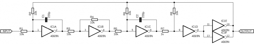
Actually, I think, that I came up with something even more elegant 🙂
As we know CD4069 can be used in linear mode (because it is always an UB variant) and has over 1MHz bandwith - ideal candidate for the modulator!
So I breadboarded the circuit in attachment, it works surprisingly well, but is a ***** to simulate in LTSpice (I don't have an accurate model of the 4069, and using random P and N MOS with source resistors is not very close to the real deal).
Oscillates ~500 kHz (depends upon VDD and the feedback capacitors), duty and frequency shifts with changes to the 'INPUT' point, output RMS tracks input (inverted of course).
So now the idea is to use the square wave output to drive optoisolated drivers (like the VO3120), driving the diodes back to back to the 0V point through a current limiting resistor. Of course feedback path to the integrators would be switched to the inverter output.
This way the thing can be scaled to stupid power levels, I think.
The real nice thing is that the whole modulator is 1 IC with a small bunch of resistors and a few capacitors and can run from 3V to 12V (+-1.5V to +-6V) (at 15V the thing might go up in flames). I think that operation at 12V is prefered though, more umph to push the FET drivers. Adding an opamp to the input to buffer and invert the signal going into the modulator might also be a good idea, I will edit my schematic.
Attachments
Last edited:
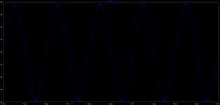
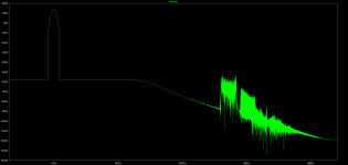
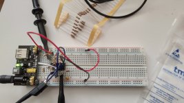
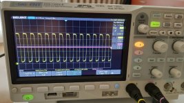
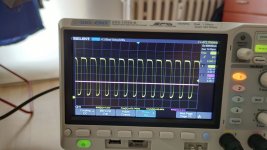
Some traces and a photo of the ungodly mess that I made on the breadboard 😀
Yellow is the modulator output, violet is the input node voltage.
Yellow is the modulator output, violet is the input node voltage.
Attachments

- Status
- Not open for further replies.