would be happy to be on your beta test tem micheal! I'm confident i would be the perfect null-measurement😉
Bas
Bas
Hello Promitheus,
have done some experimental work with metalized foils from an capacitor but that wasn't too promising: you can't corrugate very thin plastic films, so you have to stretch it and probably get a higher resonance frequency of the ribbon. Afaik traditional ribbons are made of 8 - 11 µm alu.
have done some experimental work with metalized foils from an capacitor but that wasn't too promising: you can't corrugate very thin plastic films, so you have to stretch it and probably get a higher resonance frequency of the ribbon. Afaik traditional ribbons are made of 8 - 11 µm alu.
Really?
Real life ribbons are made of ALU?
wow, I thought they were some kind of special foil or something.
Do you have an idea how thick normal Alufoil from the supermarket is?
Looking at the graph from the measurements there is a dip in the middle, do you know what parameter causes that?
Is it possible to make it flat?
Standard household alu foil seem to be between 10 and 15 µm thick (this is not the extra-strong variety but the cheapest you can get). So my self made ribbon should hopefully be only slightly heavier (and shurely a bit more strengthy) than a professional one.
The dip in the middle becomes deeper if you measure with a shorter distance between microphone and ribbon. With more distance measured frequency response will become flatter - exzept for room reflections and other stuff. I think that the measurement is influenced by the fact that sound is produced all along the ribbon at the same time but has to travel to the microphone (just a point in space) on ways of different length. (Other kinds of tweeters don't have such long membranes!) So at some frequency you will have interferences and a resulting dip in the response. The nearer the microphone comes to the ribbon the more different the ways and the deeper the dip. You should measure a ribbon at some two to three meters - but my basement room isn't long enough. So this seems to be a problem of measurement, not construction.
The dip in the middle becomes deeper if you measure with a shorter distance between microphone and ribbon. With more distance measured frequency response will become flatter - exzept for room reflections and other stuff. I think that the measurement is influenced by the fact that sound is produced all along the ribbon at the same time but has to travel to the microphone (just a point in space) on ways of different length. (Other kinds of tweeters don't have such long membranes!) So at some frequency you will have interferences and a resulting dip in the response. The nearer the microphone comes to the ribbon the more different the ways and the deeper the dip. You should measure a ribbon at some two to three meters - but my basement room isn't long enough. So this seems to be a problem of measurement, not construction.
Actualy, there's a big one near 1,5k too, but that doesn't show much because it is allready droping. If i look clos, there is a very small one at 3k
length is 200 mm , which results in a standing wave off about 1,7k
Might these be F1, F2 and F3?
Bas
length is 200 mm , which results in a standing wave off about 1,7k
Might these be F1, F2 and F3?
Bas
and how does that matter?
if the air pressure waves from the center of the foil try to null out the waves from the end or something, you get a drop don't you?
just theory...
if the air pressure waves from the center of the foil try to null out the waves from the end or something, you get a drop don't you?
just theory...
Hi Bas,
if you put your microphone at a distance of - say - 15 cm pointing to the mid of the ribbon and you have 10 cm from that midpoint to the end of the membrane (half of 20 cm ribbon length), than my Pythagoras says that the difference of the direct path from the midpoint to the microphone and the path from an endpoint of the ribbon to the microphone will be 18 cm. This makes a difference of 3 cm and that should give a dip at a frequency were 3 cm is half a wavelength. This should be at some 5700 Hz. The dip isn't very deep fore we have many points on the ribbon in between, so we have many different path lengths too and will not get perfect substraction. If you put your microphone at some new position farther away from the membrane, than the difference of the path lengths will become smaller and the dip frequency will become higher. If you could put your microphone at some point far enough from the ribbon, path difference will be so small - for a 20 cm ribbon at least - that dip frequency will be very high and out of measurement range.
if you put your microphone at a distance of - say - 15 cm pointing to the mid of the ribbon and you have 10 cm from that midpoint to the end of the membrane (half of 20 cm ribbon length), than my Pythagoras says that the difference of the direct path from the midpoint to the microphone and the path from an endpoint of the ribbon to the microphone will be 18 cm. This makes a difference of 3 cm and that should give a dip at a frequency were 3 cm is half a wavelength. This should be at some 5700 Hz. The dip isn't very deep fore we have many points on the ribbon in between, so we have many different path lengths too and will not get perfect substraction. If you put your microphone at some new position farther away from the membrane, than the difference of the path lengths will become smaller and the dip frequency will become higher. If you could put your microphone at some point far enough from the ribbon, path difference will be so small - for a 20 cm ribbon at least - that dip frequency will be very high and out of measurement range.
Just as a side note...
It occurred to me when re-building my ribbons that the supplier of the Kapton/Aluminum ribbon is completely happy to sell his ribbon material to the DIY community.
So....if you are hard up to build a ribbon...then there is a source for quality ribbon material with aluminum traces already manufactured. I beleive the material is in 1000 ft rolls and is 10 inches wide (meant to be trimed off), so you can buy it by the foot I assume.
For whatever its worth...
Cheers,
Ribbon Project
DIY Ribbon
Here comes the missing part I of my DIY Ribbon article - look at "Ribbon I" under "Lautsprecher" at http://www.michaelgaedtke.de/.
Here comes the missing part I of my DIY Ribbon article - look at "Ribbon I" under "Lautsprecher" at http://www.michaelgaedtke.de/.
Member
Joined 2003
Ilias,
Here is my version of a 25 x 1150mm x 5 micron aluminum ribbon...
tvi mentioned tape which reminded me of some drivers I made several years ago...I applied 3mm strips of foil to simple Scotch transparent tape. To avoid breaking the foil during handling, it helps to stretch the tape slightly before applying the foil.
For slitting foil, I apply 3 layers of 50mm packing tape to a glass surface, stretch the foil over the tape and use an Olfa rotary cutter (fabric shops) against a metal straight-edge. Pull both sides of the cut foil up from the tape at the same time to avoid tearing the foil.
Taping the ends of the tape and foil to the work surface maintains tension for both processes.
Regards,
Paul
Ribbon WTW project
Here is my version of a 25 x 1150mm x 5 micron aluminum ribbon...
An externally hosted image should be here but it was not working when we last tested it.
tvi mentioned tape which reminded me of some drivers I made several years ago...I applied 3mm strips of foil to simple Scotch transparent tape. To avoid breaking the foil during handling, it helps to stretch the tape slightly before applying the foil.
For slitting foil, I apply 3 layers of 50mm packing tape to a glass surface, stretch the foil over the tape and use an Olfa rotary cutter (fabric shops) against a metal straight-edge. Pull both sides of the cut foil up from the tape at the same time to avoid tearing the foil.
Taping the ends of the tape and foil to the work surface maintains tension for both processes.
Regards,
Paul
Ribbon WTW project
W O W ! ! ! 
Those are self made?
Very good job. Those look fantastic.
What does the Frequency response look like?
Those are self made?
Very good job. Those look fantastic.
What does the Frequency response look like?
Member
Joined 2003
Thanks! Yes, self made over a period of about 10 months...the prototypes actually took more time than the final versions. You can see some of the construction steps and comments on the results at the WTW link above.
Sounds like you are getting the bug. Go ahead...it's great fun!
Sounds like you are getting the bug. Go ahead...it's great fun!
Transformer for Ribbon-Speakers
Here I show how I constructed transformers for my ribbons:
http://www.michaelgaedtke.de/Ribbon_3.htm
Here I show how I constructed transformers for my ribbons:
http://www.michaelgaedtke.de/Ribbon_3.htm
Hello again,
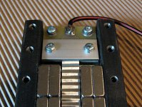
from a friend I borrowed a gaussmeter which measures the strength of magnetic fields with a probe small enough to be positioned in the gap of my ribbon speakers. Here are my findings: Fortunately the field is
a) highly concentrated in the gap
b) linear across the length of the gap; linear part begins after half of first magnet block (some 10 mm) so that total homogeneous field ist just one neodym block shorter than magnet row (9 out of 10)
c) as far as the old gauge is correct field is strong at some 0,5 Tesla (5000 Gauss) in the middle of a 12 mm wide gap between double rows of magnets - see foto.
By the way: I also tested if the field is influenced by the addition of iron pieces across the ends of the frame to close the magnetic flux in the rear of the ribbon. Varnhagen seems to be right in his finding that this doesn't make much of a difference in efficiency - I could hardly see a deflection of the meter pin.
Attachments

Usually you'll find very thin foil at manufactures of high end audio capacitors. But we warned: thin foil is very difficult to handle! My speaker function well with normal household foil (some 12 thru 15 my).
NEODYMMAGNETS
Does the magnets have to be "block"shaped ?
I got the possibility of buing round neodymmagnets 10 mm thick with a diameter of 30 mm fore a reasonable price, can i use them ?
I only want to use them for a small prototype - if possible.
Does the magnets have to be "block"shaped ?
I got the possibility of buing round neodymmagnets 10 mm thick with a diameter of 30 mm fore a reasonable price, can i use them ?
I only want to use them for a small prototype - if possible.
Round magnets
No, I don't think that to be a problem. You'll get a deeper field than needed but afais it will be reasonably linear in the middle. Maybe the deep slot will show acoutical problems, but that shouldn't matter to much - for a prototype at least.
Good luck!
Would be fine to hear about your findings.
No, I don't think that to be a problem. You'll get a deeper field than needed but afais it will be reasonably linear in the middle. Maybe the deep slot will show acoutical problems, but that shouldn't matter to much - for a prototype at least.
Good luck!
Would be fine to hear about your findings.
- Status
- Not open for further replies.
- Home
- Loudspeakers
- Planars & Exotics
- DIY Ribbon speakers ??