can be etched with hydrochloric acid solutionHello, please let me know the liquid using for chemical etching of the aluminum foil. Can i use ferric chloride which we use for etching pcbs?
safelyWhat kind of oil is used in the KBG-MN capacitors? Are they safe to take apart to harvest the foil?
I disassembled a film capacitor 470000pf 400V (orange in color) and now i have two long strips of aluminium covers with dielectric material. My question is how can i use it in order to make a ribbon diaphragm? Please note that i made ribbon headphones with aluminium foil for food wrapping with good sound.Try it, in my prototype the foil works exactly with the capacitor that I indicated and only one of its gaskets. There is no guarantee that any other foil will work.
Hello, I am looking in ebay these capacitors, but can you send me a photo of this capacitor? I found other KBG-MN, etc and i dont know which of them has the aluminium foil you described.Take capacitor KBG-HM 400V in it foil thickness of 10 microns, it will do, I have such a foil in the drivers
Hello again, I found zinc foil 0.01mm (10 micron) in Amazon.de. https://www.amazon.de/-/en/gp/product/B09CYHNBDX/ref=ox_sc_act_title_1?smid=A1KA3VVDD99CWF&psc=1
Is it suitable instead of aluminium?
Is it suitable instead of aluminium?
any KBG-MN capacitor has a suitable foil for tape drivers.
zinc foil is not suitable for tape drivers

zinc foil is not suitable for tape drivers
Last edited:
Ευχαριστώ, παρήγγειλα ένα κομμάτι από τη Ρουμανία. Εν τω μεταξύ, θα ελαχιστοποιήσω το πάχος του αλουμινόχαρτου για τα τρόφιμα με υδροχλωρικό οξύ. Θα δω τα αποτελέσματα.
I reduced significantly the thickness of aluminium foil < 10 micron with hydrochloric acid successfully. Then installed it on my transducers and the headphone plays very well. When i receive the ordered capacitor i will see farther.
Hello, I used aluminium foil for food wrapping which i etched by means of hydrochloric acid in order to reduce its thichness. The result is very good.I used an aluminum foil from a chocolate bar, which was formed and next thinned with NaOH solution to few um thickness.
Hello, i done it successfully.can be etched with hydrochloric acid solution
Hello, can you write how you opened it. I want to be ready when it arrives from Romania. Is it easy?any KBG-MN capacitor has a suitable foil for tape drivers.
zinc foil is not suitable for tape drivers
View attachment 1035935
Hello. Clamp the capacitor easily in a vise and carefully cut the case with a hacksaw for metal from the terminal side at the junction of the cover and box. Try not to immerse the hacksaw blade deep, only for cutting metal (case thickness is less than 1 millimeter).
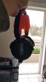
Hello, I received the Russian capacitor from Romania, I opened it with electric saw, cleaned (very high amount of oil) and cut the two pieces with width 20mm in order to make a ribbon 20 X 60mm on a 3d printed base. The result is amazing, better than aluminium foil with reduced thickness with Hydrochloric acid. Tomorrow i will send you a video with my final ribbon headphones.any KBG-MN capacitor has a suitable foil for tape drivers.
zinc foil is not suitable for tape drivers
View attachment 1035935


Hello again,any KBG-MN capacitor has a suitable foil for tape drivers.
zinc foil is not suitable for tape drivers
View attachment 1035935
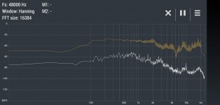
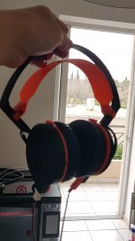
After constraction of my ribbon headphones which look as in my photo shown in my other reply, i checked the frequency response with a program in my mobile phone. So i produced signal 20 - 20000Hz and measured it. Of course the result is approximate because the measurement device is a simple mobile phone. It is significant that it has a low in 6KHz which appears in all my constructions and i must study the cause. I think if the problem can overcome by combining two membranes, one as now with width 20mm and a second with lower width 5mm for high frequencies. What are your thoughts?
Attachments
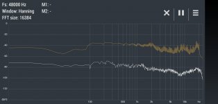
Hello again, I discovered the cause of the problem. I put on the vent of each headphone a glass fiber piece in order to prevent the outcoming air whch is possible to destroy the membrane. After removal the aproximate frequency responce is as follows:Hello again,
After constraction of my ribbon headphones which look as in my photo shown in my other reply, i checked the frequency response with a program in my mobile phone. So i produced signal 20 - 20000Hz and measured it. Of course the result is approximate because the measurement device is a simple mobile phone. It is significant that it has a low in 6KHz which appears in all my constructions and i must study the cause. I think if the problem can overcome by combining two membranes, one as now with width 20mm and a second with lower width 5mm for high frequencies. What are your thoughts?
Attachments
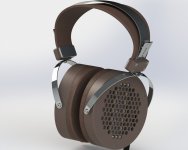
Hello, very nice headphones as I can see as construction and design. Please can you tell me why the transducers are angled in relation with ear external surface ? Also did you 3d printed it?Hello everyone. My new model.
- Home
- Amplifiers
- Headphone Systems
- DIY Ribbon Headphones