As we all know, it’s all about the bass. So I’m thinking of building a subwoofer from parts I already have lying around. Instead of using some boring ready made Class D amplifier, I want to run a beefed up 100W+ version of my Bog Standard Class AB amplifier. I have all the parts for that too, which makes it convenient.
But what about amplifier enclosure? I haven’t seen any good ones for sale. I preferably want something that doesn’t protrude too much and that would keep any accidental release of magic smoke (and heat) contained. Maybe I can use some kind of oversized junction box, but they tend to be made from pretty flimsy metal and I’m concerned they might rattle when you “pump up the jam”.
Any ideas? What are people typically doing?
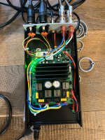
As with many plate amps it is just that, a aluminum plate with heatsink.
The transformer, rectifier, and amplifier board all attached to it.
I would say it is just being creative with the board design so the power transistors can be mounted to the plate
and a few stand offs for the whole board.
Depending on listening levels and the sensitivity of the sub 100 watts is very minimal.
You want dynamic overhead and not run the amp at high continuous power for the rail voltage.
You want 2 or 3 pairs of output devices, if not more depending on impedance.
Not only for thermal/ current reasons but actual control of the speaker.
Feedback pretty normal for any amplifier then just pile on excessive output devices for real world
gain and damping. -/+ 56 volt rails be minimum and 63 to 82 volts for more heft.
For gain to not bog down, I wouldn't accept anything but a Darlington triple to even be called a sub amp.
at least 4 output pairs. Dont matter if 60 watts or 180 watts relentless drive with healthy output sections.

Thanks for your great insight!
Unfortunately my family won’t let me go full “unn-tss, unn-tss”, so the listening levels will be quite modest. I think I’ll start at somewhere around 200W. All I want is just a bit of low end rumble to enhance the sound. Not looking to make the whole house shake.
Since my output devices are IRFP(9)240s, I might get away with doubling them if I stay at or below 200W, but maybe I shouldn’t skimp and actually triple? They’re not exactly expensive transistors.
I did consider building them on a simple plate, but I felt like I wanted to contain any possible accidents for fire safety reasons. Maybe I’m overthinking?
Faraday cage? To protect from stray EMF in the environment? Is that really something I have to worry about in a subwoofer?
Dunno? I know there are people on here who do so maybe they will chime in?
Give me a minute to find you the link…
Give me a minute to find you the link…
Here is the link to the enclosure…. FYI I ended up designing my own end covers for the input/outputs as I found it to be easier. I used Shapr3D or
Fusion…can’t remember
https://www.thingiverse.com/thing:2938921
Fusion…can’t remember
https://www.thingiverse.com/thing:2938921
Here's a quick mod of my go-to Class AB design to make it produce 200W. I have to go through all the transistors to make sure they're within their SOA, but at a first glance I would say they are.You want 2 or 3 pairs of output devices, if not more depending on impedance.
Not only for thermal/ current reasons but actual control of the speaker.
But what about amplifier enclosure? I haven’t seen any good ones for sale. I preferably want something that doesn’t protrude too much and that would keep any accidental release of magic smoke (and heat) contained. Maybe I can use some kind of oversized junction box, but they tend to be made from pretty flimsy metal and I’m concerned they might rattle when you “pump up the jam”.
Suggest the following design philosophy -
https://soundstagesimplifi.com/index.php/equipment-reviews/191-kef-kc62-powered-subwoofer
10" x 10" x 10" , -3db @ 11hz , 105 db ; 1000 Watts to pump up the jam, and not protrude too much.
Getting to be a fun straight forward amplifier.Here's a quick mod of my go-to Class AB design to make it produce 200W
Gets even more fun fine tuning.
You'll be around 112 to 118 volts so start getting past 80 volt BD139/40
I love the darn things, but higher power amps start having to let them go.
For Vas Q12 the classic KSC3503 is getting hard to get but KSC2690 is still available.
So NPN Vas we still have decent transistors.
PNP is the hard one, they dont do the matching pairs.
Then the drivers for mosfets, is possibly switch over to the Toshiba for 160 volt devices
with good speed.
TTA004,Q
TTC004,Q
I think you have the gate resistors in series. So each mosfet should just have a single 47 ohm.
Then with 6,8 volts for zener. I would sim 2.7 to 3.3 ohm loads and make sure they aren't clamping
to early near full power or clipping. Since "4 ohm" speakers will dip that low.
Much like a VI limiter you get flyback voltages if they clamp when music is playing.
If so no biggy just open them up to 8.2 volts or higher if needed.
Then if the amp is shorted they tend to offer a little current limiting as well.
Just dont want current limiting while music is playing and get flyback.
I havent simmed mosfet amps in awhile at 56 to 63 volts. Woo getting good.
I think 6.8 volts was ok on 42 volt rails.
Well, it’s a Blameless-type, so it’s about as straightforward as it gets. 😀
The series 47 ohm before the zeners is there to allow for some voltage drop when they start conducting. Without them I don’t get much overcurrent protection. They can probably use some tweaking, but current configuration limits current just above 200W.
As for the BDs, none of them should ever see more than half the rail-to-rail voltage. At least when things work as they should. I’ll check out your suggestions. I’m a bit of a one trick pony when it comes to transistor selection. I tend to stick to my 2N5551/5401 and BD139/140. I’ll widen my horizons. 😀
Im with yay, 5551/5401 139/140 are my go to, love the things.
Id rather use BD139/40 as well. For the 2nd stage /Vas that does swing past 80 volts
Worth the quick download for the spice file
For the KSC2690
THD might actually drop a little, maybe.
Most the reason is voltage tolerance
Slam it with a" 6 pack" lol.
I hardly run even 4 ohm loads in real life.
But 6 output devices would be rather sweet.
Any load any day with good swing
Last edited:
Hypex got it right when they decided to ventilate their plates. The air space of the amp should be separated and air tight relative to driver air space, seal of wire passthroughs. Then add openings to bottom and top side of the amp air space to allow natural cool intake hot exhaust into the room. This approach will solve most amp heat issues. You can even add a small fan to reinforce air movement. Such fan should direct air flow to blow hot air out of the enclosure in order to avoid dust build up.
At this point, while making such amp compartment inside a speaker cabinet is a good option, you should also consider putting the amp into a separate enclosure in a classic passive speaker way. Whatever fits your available space best and if you are planning to change any components often.
Another option would be to attach such amplifier enclosure at back, bottom or top of the actual speaker, if that's OK for your plans.
- Home
- Loudspeakers
- Subwoofers
- DIY plate amplifier enclosure