Hello, i had an idea of making my own, Phono preamp and se if i can make it sound better then my current one (heed questar) it was around 450$ when i got it. I realy dont want to buy a kit, i want to learn about it and make my own, i will do alot of stupid mistakes of that i am sure, but that might be the best way to learn.
so i looked around on preamps from my own and up to 10K preamps and thought i might be able to get some insperation in design decisions. and i found Sutherlands phono preamps and found that they got some good reviews and the design looks simple when i look at some other designs.
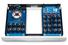
They use two separate mono preamps,For power they use alot RC filters going from 48V down to 10-15v (dont know right now) then use zener diodes for each ICs to get it down to what voltage they want, (i thought that zener made some noise and might be bad to have this late in the chain? ) They use they use ICs INA103KP for input then OPA134PA and then OPA627AP for output, the OPA627AP is not avalible anymore though........ any ideas on a replacement ? if i am going with this design that is. what do you all think, is this a good or a bad idea ?
so i looked around on preamps from my own and up to 10K preamps and thought i might be able to get some insperation in design decisions. and i found Sutherlands phono preamps and found that they got some good reviews and the design looks simple when i look at some other designs.
They use two separate mono preamps,For power they use alot RC filters going from 48V down to 10-15v (dont know right now) then use zener diodes for each ICs to get it down to what voltage they want, (i thought that zener made some noise and might be bad to have this late in the chain? ) They use they use ICs INA103KP for input then OPA134PA and then OPA627AP for output, the OPA627AP is not avalible anymore though........ any ideas on a replacement ? if i am going with this design that is. what do you all think, is this a good or a bad idea ?
Attachments
Parametric power supply (zener diodes and a lot of RC filters) is not a great idea because of zener noise and output impedance. Perhaps 3 opamps are used in next way:
1 - gain stage on INA103 (instrumental amp for MC cartridges and microphones)
2 - OPA134 as ARC (active RC filters) network
3 - OPA627 as output buffer, because it stable on unity gain and sounds great, I’ve used it same way in my DAC.
My suggestion is to replace a RC garland in PSU by simple active filter (few resistors, capacitors and transistor), since the supply current and voltage are not high you can used a JFET transistors instead of MOSFET. You can look at PSU schematic in my phono thread
Moving coil or moving magnet? INA103 is an ultralow noise voltage, ultrahigh noise current device, so it is suitable for moving coil but not very suitable for moving magnet.
On the other hand, the OPA627's noise specs make it very suitable for the first stage of an amplifier for moving-magnet cartridges, but not very suitable for moving coil.
This thread might be of interest:
This thread might be of interest:
By now it has been a while since OPA828 (and OPA2828) were released. Any detailed comparison done (in the context of audio) to the opamp, OPA627, that they are supposed to replace? Thanks!
The zener diodes is strange to me as well, they use them in all there phono stages, and it is from there "cheap" 900$ one to the phonoblock witch used to cost 10K but people that have tried them say that the noice is pitch black, dont know if the rejection is high enough to compensate this ? and as you say one can use a active filter insted, is the RC filter just for looks ? 😛Parametric power supply (zener diodes and a lot of RC filters) is not a great idea because of zener noise and output impedance. Perhaps 3 opamps are used in next way:
1 - gain stage on INA103 (instrumental amp for MC cartridges and microphones)
2 - OPA134 as ARC (active RC filters) network
3 - OPA627 as output buffer, because it stable on unity gain and sounds great, I’ve used it same way in my DAC.
My suggestion is to replace a RC garland in PSU by simple active filter (few resistors, capacitors and transistor), since the supply current and voltage are not high you can used a JFET transistors instead of MOSFET. You can look at PSU schematic in my phono thread
i use MM right now, i have an ortofont red right now but will upgrade it during the next year during this litle upgrade. hehe i asked Chat GPT and he thought that LT1028 or AD797 might be an upgrade over the INA103, true or not ?Moving coil or moving magnet? INA103 is an ultralow noise voltage, ultrahigh noise current device, so it is suitable for moving coil but not very suitable for moving magnet.
I meant ARC filter for RIAA equalization. In PSUi suggest to use mosfet or jfet based rc filter (capacity multiplier other words).and as you say one can use a active filter insted, is the RC filter just for looks ? 😛
For MM head I suggest to use AD744 at input stage, it has a very good input but weak output. To skip ad744 output stage you can use pin 5 not pin 6. Pin 5 is adjustment pin but also it is a preout output (what a weird wording??? 🙂)). Since the next stage is ARC with opamp it has a high input impedance and ad744 pin 5 is able to drive without significant distortion.
i use MM right now, i have an ortofont red right now but will upgrade it during the next year during this litle upgrade. hehe i asked Chat GPT and he thought that LT1028 or AD797 might be an upgrade over the INA103, true or not ?
Sure as hell not for moving magnet, particularly not the LT1028.

For MM you need low current noise, so NE5534A or a JFET opamp such as OPA1656. MM cartridges typically have >10k impedance at higher frequencies due to their high inductance, whereas MC are 10 ohms or so across the entire audio band, extremely different beasts...
The AD744 is very noisy for a preamp...
BTW it can be useful to integrate a rumble filter into a preamp, I've used a 4-pole Butterworth with cutoff of about 16Hz before.
The AD744 is very noisy for a preamp...
BTW it can be useful to integrate a rumble filter into a preamp, I've used a 4-pole Butterworth with cutoff of about 16Hz before.
Last edited:
hehe ahaaa sorry 🙂 is it noisy or is it okey? 🙂I meant ARC filter for RIAA equalization. In PSUi suggest to use mosfet or jfet based rc filter (capacity multiplier other words).
View attachment 1398994
For MM head I suggest to use AD744 at input stage, it has a very good input but weak output. To skip ad744 output stage you can use pin 5 not pin 6. Pin 5 is adjustment pin but also it is a preout output (what a weird wording??? 🙂)). Since the next stage is ARC with opamp it has a high input impedance and ad744 pin 5 is able to drive without significant distortion.
hehe okey ,no LT1028 then 😛Sure as hell not for moving magnet, particularly not the LT1028.
See my thread, I’ve posted measurements therehehe ahaaa sorry 🙂 is it noisy or is it okey? 🙂
Hi,
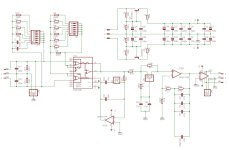
attached You find one of the many versions of a balanced input phono stage, as it is used over here, utilizing INA103, INA163, SSM2017, or THAT1570.
I prefer the INA163 over the INA103, as it is the slightly refined successor of the INA103 (which is quite old now ...I used it as part of my Thesis in 1993 already).
SSM2017 is also now a >20y old device. The THAT is practically identical to the INA163.
The latter two ones might be easier to source also and generally cost <10€/$.
Anyway ... the big pro of those INAs is that they allow for very high flexibility with regard to what Pickups one could use, variable input impedance, variable input mode bal/SE, and variable gain.
The attached circuit is a proven example and easy to build.
The INAs are optimized for input resistor values around 200Ohms and their en and in values are sufficiently low to accommodate for low output MCs (>150µV) up to high-output MMs (>5mV).
Spezialized OPAmps may have a light edge over the INAs, but in praxis INA-equipped Phono stages -DIY as well as commercial ones- typically belong to the top group regarding noise figures (see Clearaudio balanced, Lehmann, audiospecials, et al).
I couldn´t find a pickup and setup yet, where those INA-stages didn´t perform exceptionally well.
- the input may be switched between balanced and SE-mode depending on JP2 setting.
Balanced mode is advantageous for MC useage, while (some) MMs come artificially unbalanced by the manufacturer and may need user modification.
Also SE-inputs utilizing RCA connecors are the standard.
If You don´t require or want the balanced-input option then other OPAmps may fill the bill.
- with S1 You can vary the input impedance in 4 capacitive steps and 16 resistive steps.
Of course you can opt for different values und numbers of settings after Your fashion.
- R9 defines the lowest gain of the linear INA-Stage IC1.
Adding resistors in parallel with S2 increases gain from 16.7x (S2 all Off) up to 1180x (S2 all On).
- IC2A a JFET-in OPAmp drives the Ref pin of the INA with a DC-servoed signal.
Due to the possible high gains of IC1 there may occur considerable DC-Offsets ... so the DC servo is a requirement.
Here the Xover frequency can be chosen between 16Hz or <1Hz (JP3 closed)
I personally use the 16Hz setting as it forms a rumble filter, preventing excessive amplitudes of the woofers.
Also the Ref input pin should be driven by a low impedance, which the IC2As output provides for.
- R13 to R15 and C10, C11 form a passive 2120Hz network, which my be switched between standard RIAA (JP1 2-3 closed)
and a extended, higher linearity amplitude response (sometimes, but falsely so called Neumann, JP1 1-2 closed).
I typically use 0.1% NiCro thinfilm resistors here and low tolerance silver mica caps (of 10nF paralleled and different matching resistor values)
- a split RIAA network with a second active filter stage is chosen here as it offers higher replay precision, lower noise, lower THD
as well as 20dB less required gain and it offers more flexibility in the choice of parts and parts values.
- UC2B forms the 2nd gain stage with a 50-500Hz shunt feedback network.
Again a JFET-In OPAmp is a good choice when low Offets and noise are required and input impedances not only differ but vary in value over frequency.
Gain is set to ~10x @1kHz and I like to add a cap between R16 and gnd to set the DC-Gain to 1.
The HP-filter formed by this RC network I choose to be ~16Hz also, so that overall a 2nd order HP/Rumble filter response is achieved.
- If nothing else is required, a series output resistor of 27R to 47R suffices, followed by 100k to gnd to help IC2B drive capacitive loads.
Here though a SE-to-balanced driver IC is added to create a balanced output. TI, ADI and THAT offer several different suitable ICs.
If one wishes for a standalone Phono-setup a Volume Pot may be added between IC2B and the SE2Bal IC.
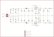
A rather common -still though at the edge of overkill- supply schem is attached also.
A small toroid, followed by discrete, denoised low trr rectifier diodes and a CLC smoothing stage.
Regs are the proverbial LM317/337, followed by a CRC filter.
Off of the PCB You can add a IEC input connector and associated power filter, power switch and Fuse.
That´s all folks.
jauu
Calvin
attached You find one of the many versions of a balanced input phono stage, as it is used over here, utilizing INA103, INA163, SSM2017, or THAT1570.
I prefer the INA163 over the INA103, as it is the slightly refined successor of the INA103 (which is quite old now ...I used it as part of my Thesis in 1993 already).
SSM2017 is also now a >20y old device. The THAT is practically identical to the INA163.
The latter two ones might be easier to source also and generally cost <10€/$.
Anyway ... the big pro of those INAs is that they allow for very high flexibility with regard to what Pickups one could use, variable input impedance, variable input mode bal/SE, and variable gain.
The attached circuit is a proven example and easy to build.
The INAs are optimized for input resistor values around 200Ohms and their en and in values are sufficiently low to accommodate for low output MCs (>150µV) up to high-output MMs (>5mV).
Spezialized OPAmps may have a light edge over the INAs, but in praxis INA-equipped Phono stages -DIY as well as commercial ones- typically belong to the top group regarding noise figures (see Clearaudio balanced, Lehmann, audiospecials, et al).
I couldn´t find a pickup and setup yet, where those INA-stages didn´t perform exceptionally well.
- the input may be switched between balanced and SE-mode depending on JP2 setting.
Balanced mode is advantageous for MC useage, while (some) MMs come artificially unbalanced by the manufacturer and may need user modification.
Also SE-inputs utilizing RCA connecors are the standard.
If You don´t require or want the balanced-input option then other OPAmps may fill the bill.
- with S1 You can vary the input impedance in 4 capacitive steps and 16 resistive steps.
Of course you can opt for different values und numbers of settings after Your fashion.
- R9 defines the lowest gain of the linear INA-Stage IC1.
Adding resistors in parallel with S2 increases gain from 16.7x (S2 all Off) up to 1180x (S2 all On).
- IC2A a JFET-in OPAmp drives the Ref pin of the INA with a DC-servoed signal.
Due to the possible high gains of IC1 there may occur considerable DC-Offsets ... so the DC servo is a requirement.
Here the Xover frequency can be chosen between 16Hz or <1Hz (JP3 closed)
I personally use the 16Hz setting as it forms a rumble filter, preventing excessive amplitudes of the woofers.
Also the Ref input pin should be driven by a low impedance, which the IC2As output provides for.
- R13 to R15 and C10, C11 form a passive 2120Hz network, which my be switched between standard RIAA (JP1 2-3 closed)
and a extended, higher linearity amplitude response (sometimes, but falsely so called Neumann, JP1 1-2 closed).
I typically use 0.1% NiCro thinfilm resistors here and low tolerance silver mica caps (of 10nF paralleled and different matching resistor values)
- a split RIAA network with a second active filter stage is chosen here as it offers higher replay precision, lower noise, lower THD
as well as 20dB less required gain and it offers more flexibility in the choice of parts and parts values.
- UC2B forms the 2nd gain stage with a 50-500Hz shunt feedback network.
Again a JFET-In OPAmp is a good choice when low Offets and noise are required and input impedances not only differ but vary in value over frequency.
Gain is set to ~10x @1kHz and I like to add a cap between R16 and gnd to set the DC-Gain to 1.
The HP-filter formed by this RC network I choose to be ~16Hz also, so that overall a 2nd order HP/Rumble filter response is achieved.
- If nothing else is required, a series output resistor of 27R to 47R suffices, followed by 100k to gnd to help IC2B drive capacitive loads.
Here though a SE-to-balanced driver IC is added to create a balanced output. TI, ADI and THAT offer several different suitable ICs.
If one wishes for a standalone Phono-setup a Volume Pot may be added between IC2B and the SE2Bal IC.
A rather common -still though at the edge of overkill- supply schem is attached also.
A small toroid, followed by discrete, denoised low trr rectifier diodes and a CLC smoothing stage.
Regs are the proverbial LM317/337, followed by a CRC filter.
Off of the PCB You can add a IEC input connector and associated power filter, power switch and Fuse.
That´s all folks.
jauu
Calvin
Attachments
INA103 has significant current noise, 2pA/√Hz compared to 0.4pA/√Hz for NE5534A, and used differentially that makes it upto 17dB noisier at high frequencies for a MM cartridge than a straightforward single-ended NE5534A circuit... Fine for MC, not a good choice for MM though in my book.
INA163 is better in that sense; about the same noise voltage specs, but only 0.8 pA/√Hz typical.
For some reason, the typical noise current specification for the INA103 is much higher than the shot noise of its input bias current, even though it doesn't seem to have bias current compensation.
For the INA163, that 0.8 pA/√Hz typical is simply the shot noise belonging to its 2 uA input bias current. Chances are it gets √2 times better with a balanced source.
Last edited:
0.8pA is better, but JFET devices finesse the issue of course, for bipolar NE5534A still rules AFAIK.
I think INA163 is a good compromise for an amplifier that has to support both MM and MC without switching input stages, if you don't want to use big JFETs.
MM: RIAA- and A-weighted source impedance about 12 kohm, so 0.8 pA/√Hz has as much impact as 9.6 nV/√Hz. The voltage noise is negligible compared to that.
MC: very low impedance, so only the 1 nV/√Hz voltage noise matters.
MM cartridges produce about 10 times more signal voltage than MC, so the signal-to-noise ratios are about equal.
If you think that compromize is worth it - a ZTX951 MC stage plus NE5534A MM/RIAA stage takes a lot to beat and are actually significantly cheaper than INA103/INA163 and are available through-hole too which matters to some people.
Also having separate MC stage allows more reasonable gain staging through the preamp so that high frequency performance isn't compromized by running out of GBP in a single high-gain stage.
It won't be terrible, but its possible to do better, cheaper, which would worry me as missing a trick.
Also having separate MC stage allows more reasonable gain staging through the preamp so that high frequency performance isn't compromized by running out of GBP in a single high-gain stage.
It won't be terrible, but its possible to do better, cheaper, which would worry me as missing a trick.
It doesn't really matter what I think, but what @Chrabban87 wants. I usually use a JFET input stage and an electrically cold input resistance realized by a double feedback loop for solid-state MM amplifiers, but others may find that over the top.
- Home
- Source & Line
- Analogue Source
- DIY phono preamp idea