magnetic bearing
Neither of the two quotes applies here:
pay attention that the theorem refers to a static / stationary condition which does not apply to the case of the bearing here. There's no reason why the bearing should not work in theory apparently. Have a look here also for more info:
http://tel.archives-ouvertes.fr/docs/00/56/92/74/PDF/these-allag-udg.pdf
on page 26. Apparently also, they're quite difficult to fabricate.
Hi doitmyself,
Here are the two most pertinent quotes from the links I posted:
Quote:
"Earnshaw's theorem states that a collection of point charges cannot be maintained in a stable stationary equilibrium configuration solely by the electrostatic interaction of the charges. This was first proven by British mathematician Samuel Earnshaw in 1842. It is usually referenced to magnetic fields, but originally applied to electrostatic fields. It applies to the classical inverse-square law forces (electric and gravitational) and also to the magnetic forces of permanent magnets and paramagnetic materials or any combination, (but not diamagnetic materials)."
Quote:
"En physique, en électromagnétisme classique, le théorème d'Earnshaw établit qu'un ensemble de charges ponctuelles ne peut être maintenu dans un équilibre stable uniquement par des interactions d'ordre électrostatique entre les charges.
Le théorème fut prouvé pour la première fois en 1842 par Samuel Earnshaw. On l'utilise couramment pour les champs magnétiques, mais il fut à l'origine étudié pour les cas électrostatiques. Il s'applique en réalité à toute combinaison de forces qui suivent une loi en 1/(r^2): les effets des champs magnétiques, électriques ou gravitationnels."
Quote:
"This theorem also states that there is no possible static configuration of ferromagnets which can stably levitate an object against gravity, even when the magnetic forces are stronger than the gravitational forces."
Quote:
"Le théorème établit par ailleurs qu'il n'existe aucune configuration statique d'aimants qui permettrait la lévitation stable d'un objet contre la gravité, même si les forces magnétiques surpassent de beaucoup la force d'attraction gravitationnelle. La lévitation magnétique est cependant possible, si on peut faire varier le champ magnétique dans le temps."
I know it looks like it makes logical sense, but it doesn't work. You either need an active control system to maintain stability, or you need to make whatever you plan to levitate out of a diamagnetic material.
The schematic you posted looks correct because you've only depicted the repulsive force of the magnets. Draw in the effects of the attractive sides of each magnet, along with the variations in the magnetic field caused by the shape of the magnets, and you'll quickly see why it's not a stable configuration
Neither of the two quotes applies here:
pay attention that the theorem refers to a static / stationary condition which does not apply to the case of the bearing here. There's no reason why the bearing should not work in theory apparently. Have a look here also for more info:
http://tel.archives-ouvertes.fr/docs/00/56/92/74/PDF/these-allag-udg.pdf
on page 26. Apparently also, they're quite difficult to fabricate.
Hi Stelios,
Magnetism is not so easy that it looks. What's why, I will proceed slowly to realise my rotating unit (part by part), but not now (not enough time).
I first want to finish my TT as it is, and so be able to do tests and improvements with it.
THANKS for all those interesting links.
Bruno
OK Guys,
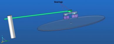
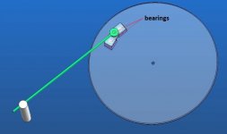
Here is the idea I had a few weeks ago. It's a little bit strange but funny as well. I would like to use 2 headshell articulated with bearings or other systems. The main one is guided with the second one.
The record will wear double.
Why not a extra axle on the arm to compensate the angle like the garrad system.
The other option could be a linear tracker, and something like the Opus 3 Cantus design comes to mind. There is a thread here about it..
http://www.diyaudio.com/forums/analogue-source/34126-opus-3-cantus-parallel-tracking-arm.html
It's elegantly simple and amenable to diy efforts, the manufacturer also sells spare parts that could be used in a diy version I suppose.
http://www.diyaudio.com/forums/analogue-source/34126-opus-3-cantus-parallel-tracking-arm.html
It's elegantly simple and amenable to diy efforts, the manufacturer also sells spare parts that could be used in a diy version I suppose.
BIM,
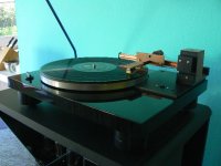
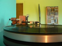
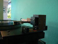
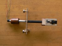
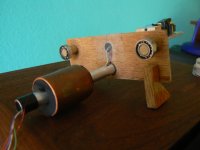
As a follow up to Kevin's suggestion, I'm posting pictures of the latest evolution of my LT design. I've gone back to the bearings/tube like the Opus Cantus, but I've put the slot at the front which allows the vertical pivot to be very low. Using just bearings - no wheels on this one - allows a wide stable carriage without a long tube. The slider gets the tube out of the way for changing records. This LT has worked flawlessly from the beginning and sounds very good. It even survived as recent audio club meeting at my house.
I had high hopes for your LT design. I'm sorry it didn't work out. With your machine skills, you should be able to make a precise and attractive version of this arm, if you are still interested in LT arms
Attachments
AuroraB
Thanks for your interest. I hope the pictures help. The bearings are 6mmx12mmx3mm from RC model cars - they are about $3 each, cheap but surprisingly good. The bearings are centered 2 3/4" (70mm) apart. The front edge of the headshell is 4 1/8" (105mm) from the carriage. The CW stub is
2 7/8" (73mm). The entire arm with the cartridge and CW weighs 55 gr.
The copper tube is ordinary 1/2" plumbing pipe. The slot was cut with a bimetal blade in a scroll saw using a jig to hold and align the pipe. The bearings just roll along the inside bottom of the tube.
This TT and LT will be at Burning Amp this weekend.
If I can be any further help, please let me know.
Attachments
Last edited:
Hi doitmyself,
How are things progressing. After a booming start of you project things got a little quite around here... unfortunately. I have been following this project with a lot of admiration and hope we will see some nice work coming from your hands again soon.
kind regards,
c.
How are things progressing. After a booming start of you project things got a little quite around here... unfortunately. I have been following this project with a lot of admiration and hope we will see some nice work coming from your hands again soon.
kind regards,
c.
Welcome!Hi friends,
And i would like to apologize. i had a big family problem (about to be solved), that's why I stopped the project. I hope to be back soon. THANKS.
Waiting for the end of your Projects,
goodness and peace of mind for you and your family.
Sincerely, Alexander
")
Hi DIM
Haven't seen this thread before, but reading/viewing the 36 sides, have left me more than impressed with your ideas, and your capability to execute them. fantastic dokumentation in piqtures, drawings and text. I think many of your readers would like to have a follow up on the progress. Also hope that the problems you mentioned in the last post have been resolved.
Regards Steen
doitmyself is on the Forum Audiophile. See his thread Realization DIY turntable.
Forum des audiophiles
Forum des audiophiles
In fact the true reborn :
Réalisation platine vinyle DIY : Réalisations personnelles - DIY - Page 28
Réalisation platine vinyle DIY : Réalisations personnelles - DIY - Page 28
- Status
- This old topic is closed. If you want to reopen this topic, contact a moderator using the "Report Post" button.
- Home
- Source & Line
- Analogue Source
- DIY Personal Turntable