

Hello doitmyself
Looking at the drawing in post #1, I noticed that the rod upon which the tone arm slides, is located well above the top surface of the vinyl LP.
Is there any reason why you could not locate the center line of that rod in the same plane as the top suface of the vinyl LP? If I understand the drawing correctly, that rod is the pivot for vertical motion of the tone arm.
Also, I would like to know the name of your CAD program.
Sincerely,
Ralf
Hi Ralf,Looking at the drawing in post #1, I noticed that the rod upon which the tone arm slides, is located well above the top surface of the vinyl LP.
Is there any reason why you could not locate the center line of that rod in the same plane as the top suface of the vinyl LP? If I understand the drawing correctly, that rod is the pivot for vertical motion of the tone arm.
Also, I would like to know the name of your CAD program.
Sincerely,
Ralf
The only reason (I don't know if good or not), is that I wanted the gravity point under the pivot axe. I saw this in different forums, but about standart tonearms. The experiments will give me some answers.
And about the CAD program: Topsolid 3D by Missler software (version 6.10). You can download a viewer version (for free), so I can post you my turntable files, if you want. Here: ftp://ftp.topsolid.com/Public/TopSolidV ... 200.22.exe
Sincerely,
Bruno
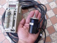
The second problem I was worrying about is solved now. Yesterday, The receller from Omron, Mr Destra, came at home with the servomotor and servodrive. High quality material. THANKS Mr DESTRA.
We use this kind of motor in our machines at my company. And this model is much more powerfull. Many ways to pilot the motor. Here is a photo to show model and size.
We use this kind of motor in our machines at my company. And this model is much more powerfull. Many ways to pilot the motor. Here is a photo to show model and size.
Attachments
Yes, that's this one .Smallest Yaskawa servo motor is 30W, no ?
DIM,
Going by the parts you have already, your TT is going to be beautiful.
I'd like to share a couple of observations based on my experience building linear tracking arms. If you are going to use O rings in the arm you may find some of them are stiff enough to transmit noise. I've found that RTV silicone or something with a similar resilience works well both to keep parts aligned and damp noise. Heat shrink tubing on the arm is a great damper.
Six inches is about the longest arm I've had any success with, but I use ball bearings and have no experience with linear bearings. The problem is that the arm is trying to torque around the bearing contact point, which can cause non-linear movement that can result in sound distortion and skipping. If the linear bearings and the longer arm work well, that would be a major achievement.
Ralf,
The question of where to place whatever carries the arm - rod, tube, V trough, etc. - and where to place the arm itself is a nasty can of compromise worms. Shorter arms seem to work better, but that puts everything right over the record surface and makes record changing hazardous unless you use a high pivot. A high pivot is out of the way but results in a peculiar headshell/cartridge movement and a low pivot with a straight through arm can mean problems with CW placement. And there are further considerations for arms placed above or below the beam.
Eventually, I settled on a low pivot, overhead arm that is roughly equivalent to the alignment of an AR xa, but because my wife was reluctant to change records, I also built a sliding tower which moves everything to the rear edge of the record. There are photos on the last page of the "Opus Cantus linear tracker" thread.
If DIM's linear bearing or your own Straight Tracker solutions pan out, most of the LT compromises will be swept away. I'm looking forward to that possibility and hope for success for both of you.
Hi Doug,DIM,
Going by the parts you have already, your TT is going to be beautiful.
And Thanks for your support.
I don't know with what are maid my O rings, I have seen in the website of the company which sales us the seals that there are 4 differents materials. When the marketing person of this company will come here, I'll ask him for more details.DIM,
I'd like to share a couple of observations based on my experience building linear tracking arms. If you are going to use O rings in the arm you may find some of them are stiff enough to transmit noise. I've found that RTV silicone or something with a similar resilience works well both to keep parts aligned and damp noise. Heat shrink tubing on the arm is a great damper.
 .
.[/QUOTE]
Six inches is about the longest arm I've had any success with, but I use ball bearings and have no experience with linear bearings. The problem is that the arm is trying to torque around the bearing contact point, which can cause non-linear movement that can result in sound distortion and skipping. If the linear bearings and the longer arm work well, that would be a major achievement.
[/QUOTE]
This is also a problem for me, I'm a total noob in arms. That's why your comments are welcome, If you see the main drawings, The arm pivot is just fixed by one screw, so I can adjust the distance from the LP's center, so I'll be able to make tests with different sizes and different arm material (aluminium, wood). About the linear bearings, I will also try to do a small video of the tests I want to do before? Actually, I'm trying to buy a second hand TT, not expensive, in order to dismantle it and take the arm for tests with onother TT (Technics Sl Q303).
[/QUOTE]
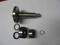
I have finished another main piece this WE, the main shaft. See photos with bearings and seals.
Are you using ball bearings for tha main platter ?
Yes, ball bearings which will move inside oil.Are you using ball bearings for tha main platter ?
Ball bearings are for the second stage platter, the main platter is separated from the seccond stage with 3 silent blocs.Are you using ball bearings for tha main platter ?
THANKS, if no problems, may be in august, I hope??Looks great, can't wait to see it come together.
I have finished another main piece this WE, the main shaft. See photos with bearings and seals.
I see the main shaft and the bearings but how do you plan to do the main contact point ? (I mean the point where the platter weight is transfered to the shaft ?)
In the first drawing I can see a one point contact... what is it made of ?
- Status
- This old topic is closed. If you want to reopen this topic, contact a moderator using the "Report Post" button.
- Home
- Source & Line
- Analogue Source
- DIY Personal Turntable