Hello all,
here's the thing: I've got an old Dual turntable, H1010SV. It has a ceramic cartridge, so the sound quality isn't that great, but nevertheless, I'd like to be able to connect this turntable to my home-stereo-amplifier.
To be able to do that I'd have to change the 2-pin-DIN-audio-connector (used to connect the output of the turntable to the speaker that's built in the turntable's case) to two RCA-plugs.
I tried to do this myself (being my first DIY audio project 🙂) and now I'm stuck 🙂
Here's what I did: I cut away the 2-pin-DIN cable, leaving the two output- connectors open on the circuit board. On those two connectors I then soldered the two RCA-cables (negative and positive terminal, leaving the earth for wat it was at first). I tried this configuration, connected the turntable to my amplifier and, despite a lot of ground noise, it worked, huray! 🙂
To get rid of the ground noise I tried to solder the earth-wires of the RCA-plugs and here things got complicated, since I couldn't find a decent grounding-spot. The metal casing that surrounds part of the circuit board (as you can see in the picture below) seemed ok (I get continuity when I connect the blue wire (negative terminal) to the case), but the solder didn't attach to it.

So first question: I searched around a bit online and found out that you should first prepare the casing with a little sand paper to make it uneven, so the solder will stick, is that correct, and if so: is the metal case ok to attach the ground wire to?
With a lot of trial and error I managed to more or less connect my ground wires (very unstable soldering, without the sand-paper-scrubbing, didn't find out about that untill later) and unfortunately my turntable didn't produce sound anymore... Problem is: I didn't know if it had something to do with soldering the ground wires or if it was something else, but to be completely certain, I decided to start over.
But then I noticed a strange thing. When I measure the voltage between the two output-connectors, I get a reading of 4.35V... for two seconds, then it drops to 4.33, then it drops, to 4.30, and so on and so on. Very slowly, the voltage keeps dropping.
This doesn't seem normal to me and for that reason I haven't tried to resolder my connectors... (on the picture you see therefore on the left side two metal bare metal dots: these are the output connectors)
I got on the phone with a friend of mine and he said that it wasn't normal and that I should try to solder a very large resistor (1Meg-ohm) from the one of the output terminals to ground to create a virtual ground and as such, the voltage between the output should become zero. But does it have to be zero?
Before I began soldering and changing the connectors, I measured the output voltage and it was 2.66V and quiet stable.
So second question: attached is the schematic of the H1010SV, what should, according to you, be the output-voltage and how do you explain that the voltage now keeps dropping very slowly. And what can I do about it? 🙂
View attachment H1010SV.pdf
I hope I've made myself clear; English is not my native language and it's quiet a complex subject to explain 🙂 But I hope someone has the time and patience to read through this thing and help me out here!
Thanks a lot!
S.
here's the thing: I've got an old Dual turntable, H1010SV. It has a ceramic cartridge, so the sound quality isn't that great, but nevertheless, I'd like to be able to connect this turntable to my home-stereo-amplifier.
To be able to do that I'd have to change the 2-pin-DIN-audio-connector (used to connect the output of the turntable to the speaker that's built in the turntable's case) to two RCA-plugs.
I tried to do this myself (being my first DIY audio project 🙂) and now I'm stuck 🙂
Here's what I did: I cut away the 2-pin-DIN cable, leaving the two output- connectors open on the circuit board. On those two connectors I then soldered the two RCA-cables (negative and positive terminal, leaving the earth for wat it was at first). I tried this configuration, connected the turntable to my amplifier and, despite a lot of ground noise, it worked, huray! 🙂
To get rid of the ground noise I tried to solder the earth-wires of the RCA-plugs and here things got complicated, since I couldn't find a decent grounding-spot. The metal casing that surrounds part of the circuit board (as you can see in the picture below) seemed ok (I get continuity when I connect the blue wire (negative terminal) to the case), but the solder didn't attach to it.
So first question: I searched around a bit online and found out that you should first prepare the casing with a little sand paper to make it uneven, so the solder will stick, is that correct, and if so: is the metal case ok to attach the ground wire to?
With a lot of trial and error I managed to more or less connect my ground wires (very unstable soldering, without the sand-paper-scrubbing, didn't find out about that untill later) and unfortunately my turntable didn't produce sound anymore... Problem is: I didn't know if it had something to do with soldering the ground wires or if it was something else, but to be completely certain, I decided to start over.
But then I noticed a strange thing. When I measure the voltage between the two output-connectors, I get a reading of 4.35V... for two seconds, then it drops to 4.33, then it drops, to 4.30, and so on and so on. Very slowly, the voltage keeps dropping.
This doesn't seem normal to me and for that reason I haven't tried to resolder my connectors... (on the picture you see therefore on the left side two metal bare metal dots: these are the output connectors)
I got on the phone with a friend of mine and he said that it wasn't normal and that I should try to solder a very large resistor (1Meg-ohm) from the one of the output terminals to ground to create a virtual ground and as such, the voltage between the output should become zero. But does it have to be zero?
Before I began soldering and changing the connectors, I measured the output voltage and it was 2.66V and quiet stable.
So second question: attached is the schematic of the H1010SV, what should, according to you, be the output-voltage and how do you explain that the voltage now keeps dropping very slowly. And what can I do about it? 🙂
View attachment H1010SV.pdf
I hope I've made myself clear; English is not my native language and it's quiet a complex subject to explain 🙂 But I hope someone has the time and patience to read through this thing and help me out here!
Thanks a lot!
S.
Hi, S:
I'm sure I'm not the most qualified to help you out here, but please indulge me while I offer my comments.
If I understand your description correctly - and referring to the schematic you posted, it looks like you're trying to adapt the (mono) speaker-level output of the built-in (mono) amplifier to stereo line-level signals that you can plug to your home stereo inputs. While there surely is a way to do this, it would - in my opinion - not be the easiest or optimal way to go.
Instead, it looks like the manufacturer has provided a connection point to take the signal directly from the ceramic cartridge, that being shown at the very left side of the schematic as "socket with closed contact for miniature plug". Can you locate that socket, and either make a cable with RCA plugs on one end for your stereo amplifier input, and the plug to match the turntable socket at the other end? (Contact "5" is Left Signal, Contact "1" is Right Signal, and the un-numbered contact is Ground.) Alternatively, you could solder the wires at the turntable end. In either case, make sure that the switch between "1" & "5" is open in use, or you will have only a mono signal at both outputs.
It's been a long time since I played with ceramic cartridges, but I do recall that they have a higher output that will likely overload the typical Phono inputs on modern amplifiers (these are made for magnetic cartridges), but if you plug them to a Aux. or similar line-level input you won't get the proper RIAA equalization. Perhaps a simple resistor network might be employed to reduce the signal level to allow it's use with a magnetic cartridge Phono input.
Again, I'm sure others will be able to offer more specific advice, but I hope this is at least of some help for now...
Good luck,
Wilf
Hi, S:
I'm sure I'm not the most qualified to help you out here, but please indulge me while I offer my comments.
If I understand your description correctly - and referring to the schematic you posted, it looks like you're trying to adapt the (mono) speaker-level output of the built-in (mono) amplifier to stereo line-level signals that you can plug to your home stereo inputs. While there surely is a way to do this, it would - in my opinion - not be the easiest or optimal way to go.
Instead, it looks like the manufacturer has provided a connection point to take the signal directly from the ceramic cartridge, that being shown at the very left side of the schematic as "socket with closed contact for miniature plug". Can you locate that socket, and either make a cable with RCA plugs on one end for your stereo amplifier input, and the plug to match the turntable socket at the other end? (Contact "5" is Left Signal, Contact "1" is Right Signal, and the un-numbered contact is Ground.) Alternatively, you could solder the wires at the turntable end. In either case, make sure that the switch between "1" & "5" is open in use, or you will have only a mono signal at both outputs.
It's been a long time since I played with ceramic cartridges, but I do recall that they have a higher output that will likely overload the typical Phono inputs on modern amplifiers (these are made for magnetic cartridges), but if you plug them to a Aux. or similar line-level input you won't get the proper RIAA equalization. Perhaps a simple resistor network might be employed to reduce the signal level to allow it's use with a magnetic cartridge Phono input.
Again, I'm sure others will be able to offer more specific advice, but I hope this is at least of some help for now...
Good luck,
Wilf
Hi Wilf,
thanks for the very helpful reply. It's actually funny you mention this solution, because that was wat I first intended to do (before I knew I had a ceramic cartridge). I asked it somewhere on another forum (gearslutz.com), where some guy pointed out to me that I had a ceramic cartridge and that therefore the level would be indeed too high for using RCA-jacks in a phono-input. He suggested I should solder the RCA connectors accross the 2 pin DIN and try it in an aux-input and so I did, and now here I am 🙂
But, indeed, there's still the possibility to try and solder RCA-jacks to the "socket with closed contact for miniature plug". That "miniature plug" by the way is some of the weirdest connectors I've ever seen; looks like a bit like a 4 pin DIN with a larger extra 5th hole at the bottom, so soldering two connectors (RCA on the one side and the weird thing on the other) isn't really an option, but maybe, as you suggest, I can solder them directly to the turntable end.
However, I don't know how loud/quiet this will sound on an AUX input. According to the guy on gearslutz (and also according to you) it will definitely be too loud on a phono-input, but aux may be an option. But, if I understand the schematic correctly, this means that I will capture the sound directly from the record BEFORE any applied filtering (there's a two-band EQ on this turntable), yes? Not that this EQ is that great, but comes in handy sometimes...
Nevertheless, still wondering why MY solution (soldering the rca to the two-pin-din connectors) doesn't work. I've already figured out that the bleeding voltage on the connectors is due to the output capacitor C12 charging, but, regardless this fact, I still don't understand why these two connectors don't give any audio output anymore. You say this "is not the easiest way to go", why not? And how can you tell it's a mono-amplifier?
I've got a bit of time this weekend, I'm going to try out your solution and let you know what it did. If, in the meantime, you got any time and wisdom left regarding the above questions, feel free to share them! 🙂
Thanks!
Senne
It sounds like you need to know the pin-out of your strange connector. If you can provide a pic of it, maybe people can help you out.
As for your ground, I would advice against soldering directly to teh chassis. Usually chassis and ground are connected through a terminal that is screwed to the chassis (or bonded in another mechanical way, like welding). this for the reasons you experienced yourself. The slowly dissipating voltage seems to indicate a current leak, possibly teh result of grounding.
For reference, a normal turntable usually has a ground terminal that you should connect to your amp so both units have teh same groun. This clears up the signal.
Some people would argue that this could result in ground loops as yoru amp is usually grounded through teh earth connection on its plug, and your turntable usually has teh same. In theory this could result in earth loops, but in practice, well, the earth of the amp and teh earth of the turntable are the same earth in your house, unless you have dodgy electrics in your house (in which case you have a bigger concern than your turntable!), and as a result those earths should be exactly the same.
It sounds like you need to know the pin-out of your strange connector. If you can provide a pic of it, maybe people can help you out.
As for your ground, I would advice against soldering directly to teh chassis. Usually chassis and ground are connected through a terminal that is screwed to the chassis (or bonded in another mechanical way, like welding). this for the reasons you experienced yourself. The slowly dissipating voltage seems to indicate a current leak, possibly teh result of grounding.
For reference, a normal turntable usually has a ground terminal that you should connect to your amp so both units have teh same groun. This clears up the signal.
Some people would argue that this could result in ground loops as yoru amp is usually grounded through teh earth connection on its plug, and your turntable usually has teh same. In theory this could result in earth loops, but in practice, well, the earth of the amp and teh earth of the turntable are the same earth in your house, unless you have dodgy electrics in your house (in which case you have a bigger concern than your turntable!), and as a result those earths should be exactly the same.
Thanks; I'll try to spot the ground terminal and connection to the chassis. Tonight I'll upload more pics. About the connector: I've showed it already to some people who know more 'bout electronics than myself and they all had the same reaction: "what the hell is that?" 🙂 But soldering directly to the table should be possible I guess.
About the leaking current: could this be the reason why my audio signal to the two bare connectors (where the 2pinDin used to be) doesn't work anymore? And if so: is there a way to "repair" this?
Thx!
Hi, Senne:
ksporry's comments about grounding are good points. If you study the schematic diagram you provided, you'll see that the circuit reference ground buss is the continuous long line going left-to-right near the bottom of the upper diagram. A lot of the circuitry has connections to that, including the ground pin of the miniature socket, right through to pin 2 of the loudspeaker socket. Right above the symbol for Motor (letter "M" in a circle), you can see the symbol for "Earth Ground". In context, I would be almost certain that this indicates an existing connection to the metal chassis of the unit. So, you could connect/solder to any convenient point of the circuit that connects to the reference ground buss, including pin 2 of the DIN Speaker socket. It is indeed important to get a very low resistance connection here for a clean signal.
To answer your question about how I know it's a mono amplifier:
Well, the left- and right-channel outputs from the cartridge are connected together to a single point in the circuit through that little switch integral with the miniature socket. The one signal then goes on through the various amplifier circuitry and plays through a single speaker, correct? (Sometimes a schematic diagram will omit showing the second channel circuitry if left/right are identical, but there is usually some note to that effect, and I see no indication of that on your diagram.) That raises a question: For your attempted connection of 2 RCA cables out to your home stereo amplifier, did you connect both of them together in parallel to the DIN speaker socket terminals - Centre wire to Pin 1; Outer wire (shield) to Pin 2 (= Ground)? If so, I can't guess why it's no longer working... just double-check everthing with an ohmmeter for starters. It's possible that the inner-wire insulation was melted by soldering, making a short to ground... If your outboard amplifier has a "Mono" switch, you could simplify your work by making just one output cable.
As you've already said, you won't get optimal performance with a ceramic cartridge. Have you considered upgrading that to a suitable magnetic cart.? I don't know about your model in particular, but the Dual 1009, 1019, etc. tonearms are very cabable of handling a decent magnetic cart. I have myself upgraded a 1009 with a Shure M44-7 tracking below 3 grams, and it works fine - lots easier on the records too.
Would you care to share some pictures of the unit? Two of my favorite references: dual-reference.com and vinylengine.com have no particulars on that model, and perhaps we could offer them your pictures and schematic diagram for their archives.
Best regards,
Wilf
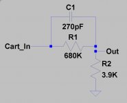
Ceramic cartridges provide inherent RIAA equalization as a function of their design, so you do not need (and should not) plug it directly into conventional RIAA equalized phono inputs. Normally you would use a line level input with a high input impedance (solid state amps generally do not have high enough input impedances, but many tube amps will) - in some cases older amps provided both an input for a ceramic cartridge as well as a magnetic cartridge which simply inserted an RC network between the ceramic input and the magnetic input circuitry. You might be able to find the details for such a network and make an adaptor..
Despite some of the schematics showing simple resistive dividers on the web this is not really what you want to do. (Excessive cartridge loading and inaccurate frequency response is likely)
Here is one possibility for a network that should provide the right EQ and loading for a ceramic cartridge using a conventional magnetic input. Originally from Audiokarma: AudioKarma.org Home Audio Stereo Discussion Forums - View Single Post - Moving magnet and ceramic phono inputs
You definitely want to grab the signal at the cartridge as you will get stereo and avoid the obviously low quality SS signal path in this thing. In the short run its a good way to get your feet wet with vinyl, in the longer run you will probably want to get a better TT with a magnetic cartridge.
Note that I have not tried this network, but it should work to at least some extent with most magnetic cartridge inputs. Some tweaking may be required. I would build this on some perf board, and use the closest value 1% 1/4W metal film resistors and a 5% polystyrene 100V cap. One required per channel.
Attachments
Last edited:
The purpose of C12 is to block any DC voltage to the output, in other words, it is an AC coupling capacitor. As you have determined C12 may be bad. You should replace all the electrolytic (metal can) capacitors because after about 40 years or so they may be very leaky and pass DC voltage or even open circuit and not pass any voltage (the electrolyte inside the capacitors dries out after so long). Also check that the potentiometer (volume control) P1 makes good contact and is passing a signal, an old volume control often has poor contacts (you can try wiping it back and forth to clean the contacts or if that doesn't work, spray cleaner solution inside).
Hi, Senne:
ksporry's comments about grounding are good points. If you study the schematic diagram you provided, you'll see that the circuit reference ground buss is the continuous long line going left-to-right near the bottom of the upper diagram. A lot of the circuitry has connections to that, including the ground pin of the miniature socket, right through to pin 2 of the loudspeaker socket. Right above the symbol for Motor (letter "M" in a circle), you can see the symbol for "Earth Ground". In context, I would be almost certain that this indicates an existing connection to the metal chassis of the unit. So, you could connect/solder to any convenient point of the circuit that connects to the reference ground buss, including pin 2 of the DIN Speaker socket. It is indeed important to get a very low resistance connection here for a clean signal.
...
As you've already said, you won't get optimal performance with a ceramic cartridge. Have you considered upgrading that to a suitable magnetic cart.? I don't know about your model in particular, but the Dual 1009, 1019, etc. tonearms are very cabable of handling a decent magnetic cart. I have myself upgraded a 1009 with a Shure M44-7 tracking below 3 grams, and it works fine - lots easier on the records too.
Would you care to share some pictures of the unit? Two of my favorite references: dual-reference.com and vinylengine.com have no particulars on that model, and perhaps we could offer them your pictures and schematic diagram for their archives.
Best regards,
Wilf
Thanks. I was already familiar with the dual-reference.com website, but indeed, no pics of the H1010SV. I've attached some more pics of the turntable (turntable with speakercase
 , weird connection (under the 2pindin)
  , cartridge
  ). About grounding: I've noticed that all the connections are in some way grounded to the (metal) back of the pot-meters (volume and tone). So I could try to attach my RCA-connectors to one of the grounding-cables that run from the connectors to the pot-meters' back. Changing the cartridge may be an option, I don't know enough about turntables to know if this would be possible. Picture of the tone-arm and cartridge also attached, perhaps you could say if this would be possible? That would be a nice solution indeed!
The thing with the "strange connector" is that it has 5 connection points: two are used for right/left signal that comes from the cartridge, one is used to connect the grounding cables that come from the cartridge (don't see anything else attached to that point), one has nothing attached to it and the last one is used to attach the cable that comes from the volume pot. So, this made me think: if I solder the new cables directly to the cartridge (ignoring this 5-point connector), volume control on the turntable won't be possible I guess? I can control the volume with my amplifier of course, so in the end, that's not really a problem, just want to make sure I understand this correctly.
By the way: if what you say is right (which I assume it is 🙂 then I didn't connect my RCA cables to the 2 DIN connection points the right way. I connected the center left cable to Pin1, center right cable to Pin2 and two grounding cables to the metal chassis. So probably I did something bad, but since I will leave the 2 DIN connectors alone, it's not that important anymore.
Ceramic cartridges provide inherent RIAA equalization as a function of their design, so you do not need (and should not) plug it directly into conventional RIAA equalized phono inputs. Normally you would use a line level input with a high input impedance (solid state amps generally do not have high enough input impedances, but many tube amps will) - in some cases older amps provided both an input for a ceramic cartridge as well as a magnetic cartridge which simply inserted an RC network between the ceramic input and the magnetic input circuitry. You might be able to find the details for such a network and make an adaptor..
Despite some of the schematics showing simple resistive dividers on the web this is not really what you want to do. (Excessive cartridge loading and inaccurate frequency response is likely)
Here is one possibility for a network that should provide the right EQ and loading for a ceramic cartridge using a conventional magnetic input. Originally from Audiokarma: AudioKarma.org Home Audio Stereo Discussion Forums - View Single Post - Moving magnet and ceramic phono inputs
You definitely want to grab the signal at the cartridge as you will get stereo and avoid the obviously low quality SS signal path in this thing. In the short run its a good way to get your feet wet with vinyl, in the longer run you will probably want to get a better TT with a magnetic cartridge.
Note that I have not tried this network, but it should work to at least some extent with most magnetic cartridge inputs. Some tweaking may be required. I would build this on some perf board, and use the closest value 1% 1/4W metal film resistors and a 5% polystyrene 100V cap. One required per channel.
If I can't change the cartridge, this seems like a very nice option. Take two cables from the cartridge, connect them to two of these networks (thereby connectiing the grounding cables from the left/righ cartridge signal directly to the turntable, right?) and then take the output of the two networks, connect two RCA plugs and try it on a phono input, right? I should be able to do this 🙂
The purpose of C12 is to block any DC voltage to the output, in other words, it is an AC coupling capacitor. As you have determined C12 may be bad. You should replace all the electrolytic (metal can) capacitors because after about 40 years or so they may be very leaky and pass DC voltage or even open circuit and not pass any voltage (the electrolyte inside the capacitors dries out after so long). Also check that the potentiometer (volume control) P1 makes good contact and is passing a signal, an old volume control often has poor contacts (you can try wiping it back and forth to clean the contacts or if that doesn't work, spray cleaner solution inside).
This is also nice to know. Contact at P1 seems good, if I don't use the amp-network in the turntable anymore, changing the capacitors might not be necessary, since I'll probably take the signal directly from the cartridge, but it's nice to know and might come in handy...
Equalization and Ceramic Carts.
The ceramic cartridge -by its very nature- is more or less self equalizing for the RIAA curve, and does not have to have an equalization network, and in addition to that is much higher output than any magnetic cartridge, thus was the cartridge of choice for 90% of all inexpensive consoles and portable phonographs. You can just plug your ceramic cartridge into the line-input of most amplifiers and have "reasonably" good sound, as good as a ceramic cartridge can deliver. Many entry level portable phonographs in the 1950's were made with a 1 tube amplifier, typically a 50L6, or 35L6, and a silicon or selinium diode rectifier for the B+. The cartridge drove the output tube directly (thru a volume control) with no preamplifier needed.
The ceramic cartridge -by its very nature- is more or less self equalizing for the RIAA curve, and does not have to have an equalization network, and in addition to that is much higher output than any magnetic cartridge, thus was the cartridge of choice for 90% of all inexpensive consoles and portable phonographs. You can just plug your ceramic cartridge into the line-input of most amplifiers and have "reasonably" good sound, as good as a ceramic cartridge can deliver. Many entry level portable phonographs in the 1950's were made with a 1 tube amplifier, typically a 50L6, or 35L6, and a silicon or selinium diode rectifier for the B+. The cartridge drove the output tube directly (thru a volume control) with no preamplifier needed.
Hi, Senne:
ksporry's comments about grounding are good points. If you study the schematic diagram you provided, you'll see that the circuit reference ground buss is the continuous long line going left-to-right near the bottom of the upper diagram. A lot of the circuitry has connections to that, including the ground pin of the miniature socket, right through to pin 2 of the loudspeaker socket. Right above the symbol for Motor (letter "M" in a circle), you can see the symbol for "Earth Ground". In context, I would be almost certain that this indicates an existing connection to the metal chassis of the unit. So, you could connect/solder to any convenient point of the circuit that connects to the reference ground buss, including pin 2 of the DIN Speaker socket. It is indeed important to get a very low resistance connection here for a clean signal.
To answer your question about how I know it's a mono amplifier:
Well, the left- and right-channel outputs from the cartridge are connected together to a single point in the circuit through that little switch integral with the miniature socket. The one signal then goes on through the various amplifier circuitry and plays through a single speaker, correct? (Sometimes a schematic diagram will omit showing the second channel circuitry if left/right are identical, but there is usually some note to that effect, and I see no indication of that on your diagram.) That raises a question: For your attempted connection of 2 RCA cables out to your home stereo amplifier, did you connect both of them together in parallel to the DIN speaker socket terminals - Centre wire to Pin 1; Outer wire (shield) to Pin 2 (= Ground)? If so, I can't guess why it's no longer working... just double-check everthing with an ohmmeter for starters. It's possible that the inner-wire insulation was melted by soldering, making a short to ground... If your outboard amplifier has a "Mono" switch, you could simplify your work by making just one output cable.
As you've already said, you won't get optimal performance with a ceramic cartridge. Have you considered upgrading that to a suitable magnetic cart.? I don't know about your model in particular, but the Dual 1009, 1019, etc. tonearms are very cabable of handling a decent magnetic cart. I have myself upgraded a 1009 with a Shure M44-7 tracking below 3 grams, and it works fine - lots easier on the records too.
Would you care to share some pictures of the unit? Two of my favorite references: dual-reference.com and vinylengine.com have no particulars on that model, and perhaps we could offer them your pictures and schematic diagram for their archives.
Best regards,
Wilf
It's been a while since my last post, but I just wanted to let you know it finally works! 🙂 I've replaced the ceramic cartridge with a magenetic one (as you suggested), soldered RCA cables to the inside of the turntable, replaced the old (completely worn out) cables that ran from the cartridge through the tonearm-pipe to the inside of the turntable, connected everything et voila!
Thanks a lot for all the help; I'm now planning to relubricate and re-adjust some of the mechanical parts, but I'll probably start a new thread about that!
- Status
- Not open for further replies.
- Home
- Source & Line
- Analogue Source
- DIY Old turntable, green-behind-the-ears-questions