I found a source for PC solder pins that work with Novar tubes so I designed a circuit board for a Novar damper diode power supply. It can be used in a hybrid bridge configuration or with a center-tapped xfmr by just leaving out the diodes. Also, the heaters can be powered by a separate or common supply by installing a couple of jumpers.
These are not for sale, but to get an idea of the cost, the boards were $2.00 each including shipping. The pins are $0.66 each. I only populated the active pins, 5 pins per tube. The PC terminal blocks are about $8.00. So the cost comes out to about $17.00 for the whole thing.
This may be overkill but I think it's a neat idea. Makes the terminations easy.
Scott
Attachments
Looks nice.
Are those Mill-Max sockets?
What part number?
If you find that there is not enough creepage distance between filament traces and the HV section you can cut a slot in the cct board with a thin dremmel cutoff disc.
🙂
Are those Mill-Max sockets?
What part number?
If you find that there is not enough creepage distance between filament traces and the HV section you can cut a slot in the cct board with a thin dremmel cutoff disc.
🙂
Thanks.
The pins are Keystone Part #1434, .032 (.81) - .046 (1.17)
https://www.alliedelec.com/images/products/datasheets/bm/KEYSTONE_ELECTRONICS/70182421.pdf
Thanks for the tip.
The pins are Keystone Part #1434, .032 (.81) - .046 (1.17)
https://www.alliedelec.com/images/products/datasheets/bm/KEYSTONE_ELECTRONICS/70182421.pdf
Thanks for the tip.
Looks good! That PCB makes the 6CJ3 a serious option. Consider, if necessary, changing the SS diode hole spacing to allow the use of Cree C4D02120A 1200 PIV Schottky diodes. Totally noise free operation and the absolute ability to handle serious voltage would be the result.
Yes, the 6CJ3 is a little beefier than the 6CL3/6CK3. I don't know what you are thinking about as far as "serious voltage". I designed this based on a ~500V B+ max so maybe the trace spacing might need to be adjusted? I did put in the diode footprint for both UF4007 & UF5408. I'm pretty sure that Cree device will fit as is with a little coaxing, but yes it would be good to put in the correct hole spacing.
What have you found regarding the heatsink requirements for the Cree device?
What have you found regarding the heatsink requirements for the Cree device?
Since you say they are not for sale, does that mean you have other intentions for the design, or are you willing to share the PCB layout and parts list? Just wondering since I use 6CJ3's and this would be a great board to have on the shelf for future projects. It might be a good candidate for a group buy if enough interest.
Thanks,
John
Thanks,
John
Hi John,
Since this is not the vendors forum I just wanted to make sure the moderators were aware that I wasn't trying to sell a product here. I can post the Gerber files for the design, no problem. It's a very simple layout. I just made these for my own use since I just bought a bunch of damper diodes. They are cheap you know, and almost indestructable at the voltages and currents that I typically use. The only parts you need are the pins, diodes, terminal blocks, and the RC across the diode if you use the hybrid configuration. I posted the pin part# above in post #3. The only downside is that you have to buy quantity 100.
I'm at work right now, let me gather all the other info together and I'll post it later today or in the morning.
Scott
Mouser Electronics also has the pins in any quantity. Small quantities are a bit more, but much less that buying 100. Can you share the PCB supplier you used? How many boards did you have to buy as a minimum?
Thank you
Thank you
The PC boards come in quantities of 10. I ordered the standard 1 oz. copper.
PC board service
ITEAD Studio 2Layer Green PCB 5cm x 10cm Max
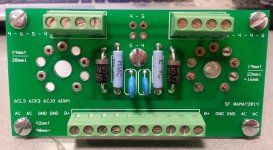
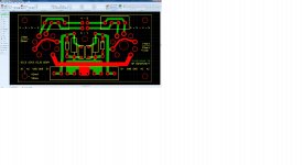
The image is looking from the top of the board. Red traces top, green traces bottom.
4 position terminal block
1729034 Phoenix Contact | Mouser
10 position terminal block
1729092 Phoenix Contact | Mouser
1M 1W resistor
VR68000001004FAC00 Vishay / BC Components | Mouser
0.01uF 2kV ceramic
564R20GAS10 Vishay / Cera-Mite | Mouser
1N5408 diode
1N5408 Taiwan Semiconductor | Mouser
PC board service
ITEAD Studio 2Layer Green PCB 5cm x 10cm Max
The image is looking from the top of the board. Red traces top, green traces bottom.
4 position terminal block
1729034 Phoenix Contact | Mouser
10 position terminal block
1729092 Phoenix Contact | Mouser
1M 1W resistor
VR68000001004FAC00 Vishay / BC Components | Mouser
0.01uF 2kV ceramic
564R20GAS10 Vishay / Cera-Mite | Mouser
1N5408 diode
1N5408 Taiwan Semiconductor | Mouser
Attachments
Very cool. I refuse to pay these ridiculous ebay prices for real B9E Novar NOS sockets. It will be fun to make my own sockets, just the socket part, chassis mountable, from PCB. I will probably use 4 layer board with thru holes isolated, the 4 layers of copper will make my homemade sockets very rigid. Just brainstorming now, I can make them with three chassis mounting screws instead of two for even more rigidity, undermount. Probably clear all the copper from the top layer against the chassis. Glad I found this post!
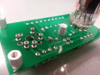
When soldering the sockets, put them on the pins of a dummy tube (bad?) and insert them in the board to solder them. This will keep them in proper alignment.
good idea! But I will attempt to get perfect holes too so the keystone pins will not have much play at all in the PCB and tube aligns perfectly. To make perfect holes in a circle I create a 10 sided polygon of the exact diameter of the Novar tube, then I just snap the pcb pads over each vertex, leaving one empty, then I delete the polygon.
- Home
- Amplifiers
- Tubes / Valves
- DIY Novar Socket