Just an idea I'm toying around, but I was wondering how hard it would be to make a quality DIY tube amp. I have 0 experience in this so I'm guessing it's a no go. On the other side I could look for someone to build the more complex electrical parts, and do the rest (woodworking and acquiring parts) of the amp myself. Are there people and/or builds of people who have done this before? I could also build like 5 (or 7) monoblocks of course if there are some good value DIY sets out there.
I have been recommended 3A4 tubes so I'm guessing using those would be a good way to base on. Would need only 1-2 watts/channel. Not sure if I need 5 or 7 channels at the moment.
Budget (to make it worthwhile) would have to be around 1000-1200 euro if possible.
I have been recommended 3A4 tubes so I'm guessing using those would be a good way to base on. Would need only 1-2 watts/channel. Not sure if I need 5 or 7 channels at the moment.
Budget (to make it worthwhile) would have to be around 1000-1200 euro if possible.
How about these kits from reputable maker? Probably you can do all by following the instructions and supply your own parts as suggested by the manufactures of PCB board. It's easy to calculate the total costs, buy only the quality you need now and add more later.
ZKIT2 / Zen Triode SET multi channel tube amplifier kit
EDCOR - GXSE Series Output Transformers
ZKIT2 / Zen Triode SET multi channel tube amplifier kit
EDCOR - GXSE Series Output Transformers
There are SO many ways you could go. But let's start with the first - and SERIOUS part of working-with-tubes that definitely can kill you. Like “death”.
Tube amplifiers, in just about all cases, use quite high voltages (compared to solid state). For instance, using commonplace tubes, inexpensive-yet-quite-good ones, you will find your first stage, commonly known as the 'voltage gain' stage to have a +250 or so power supply rail. Get a shock from that, and you'll definitely know you've done something bad. But it tends not to be lethal.
However, from a long line of practical engineering, you'll also find that each subsequent stage of the amplifier has a supply rail at a higher voltage than the previous one. By maybe 20 to 30 volts higher. So, if the input stage is 250 volts, expect the next stage, the “intermediate gain” (or phase inversion for push-pull amps) to be powered at 2275 volts. This is not done because we like high voltage, but because tubes are high impedance devices that work best at elevated voltages. Most of them.
Then you'll have a 'final' stage, in a minimalist design. Its the heavy lifter, not the voltage-swing amplifier. Different kind of tube used, acting as a current-amplifier mostly. As before, it'll be powered with a higher voltage than the previous stage, some 300 to 350 (or WAY higher, if you dare!) volts. If 250 can knock your arm 'off' (not literally), then 350 volts can knock YOU across the bench. 500 volts, and you run a chance of dying because you cannot unclamp your arm from the electrocution point. Above that, you're in wish-upon-a-star survivability.
_______
But that's the start. The next is, there is almost no way for a newbie at this to "get the circuit hooked up right" the first time around. You might. But with almost certainty, you'll accidentally touch two wires inside together that shouldn't be. Or you'll make a nearly invisble solder-blob-bridge across two separate components. Something like that. You may well hook capacitors (many of which are polarized, or polarity sensitive) backwards. You'll get the power supply rectifiers backwards. Something.
As an example: I am totally experienced building amps, electronics, electric controls. And I still make little dumb errors.
The point isn't so much that “little dumb errors” are going to ruin your day (and possibly the components, tho' many are quite robust), but that to succeed, you will have to find, to ferret out the problems, step, by step. This too isn't that hard of a thing to so, but like so many things in the technical world, it takes experience, and a steady hand, tooling and a 'sense of what it should be'. Offputting? No? GREAT! You'll do well if solving puzzles is your hobby. You'll do even better if you try some smallish projects first, then the amplifiers.
But moving on, the first lesson is “don't believe in magic components”. The 3A4 tube isn't magic. Its a tube. Its a PENTODE, or 3 grid vacuum valve. It has an now-somewhat-odd voltage for its filament (heater) of 2.8 volts. Its old enough to be in the Tube Museum, and it was in service from 1947 thru the 1960s. Is it "good"? Yes. It is good as pentodes go. Its good as a pentode for what pentodes are best used for. Is it an all-in-one-answer, definitely not.
_______
Are you still with me?
Then let's look at how you might begin.
[1] Budget
Your budget is fine. €1,000 is fine. You might be able to get 5 channels done with that, if you use “hybrid amplifier” design methods (i.e. not strictly tube from power supply to finals).
[2] First steps
Build a power supply, capable of driving the lot. If you want (say) 5 watts of output power from each of 5 similar amplifiers (its a good goal), then you'll need at least 30 watts of power-supply power for each of them. 150 watts. You should figure on minimally 3 tubes per amplifier. No tubes for the power supply, all solid state. Quite without knowing what the design is, its OK to assume … 250 V, 275 V and 350 V DC power for the 3 kinds of sections. The power supply also needs to output 6.3 VAC for the filaments of the tubes, the heaters.
Choose a design - also very important. There are without exaggeration, hundreds and hundreds of really competent minimalist amplifier designs and schematics here on DIYaudio. There are just as many outside this site. HOW TO CHOOSE? Well, on the simple side, you have (by my advice) have constraints.
× 6.3 VAC or 12.6 VAC-center tapped filaments on the tubes.
× 250 and 275 volt front end and intermediate stage.
× 350 volt final.
× 5 watts output. Probably "single ended" (meaning not using a pair of tubes in “push pull” configuration)
• Normal input levels ( 0.6 VAC to 2.5 VAC audio sources );
• Quality amplification
• “Normal” selections of tubes.
That'll whittle down the selections to perhaps scores (20, 40, 60 … ) of designs. You will find “spud” amplifiers that do it all with ONE tube per amplifier … because in the 1960s with the rise of semicoductors, the tube folks saw that their only competitive response would be to combine 2 or more valves per glass bottle. So, in essence, you can find dual pentodes, dual triodes, pentode-triode couples, and even a few triode-triode-pentode combinations. They're called “spud” amplifiers 'cuz the big-bottle tubes kind of look like glass potatoes.
Modify your idealism as you learn more. Maybe revise your expectations of power output per channel. Maybe decide to use a non-tube "final" to avoid some of the biggest-ticket issues (output transformers). Maybe all these and more. Maybe using a hybrid approach where the “sweet harmonic signature” of a tube amplifier is confined to the first and second stages, the voltage and compensation stages. Maybe even running these well below 250 and 275 volts, but closer to a much less lethal 100 or so, both. It CAN be done, and the results CAN be quite pleasing.
[3] Research the Transformer
So now you're onto actually deciding how to build that power supply. The design is chosen. You've listend to advice, talked yourself into an ideology and a design. The power supply specifications are now set. Look up common power transformers, and choose the one that's closest (and larger) than your predicted power supply demand. Maybe 50% larger. While you may some day feel miffed about spending an extra twenty quid on an over-size power transformer, you'll not have to experience the total mind-fûque of having to upsize the transformer you bought if it is too small.
[4] Build the supply
Make a wooden square with a somewhat thick aluminum cover-sheet. Upon this sheet you will build the power supply. While you're at it, purchase some large, heavy, high power resistors to use as “artificial loads” to aid in the testing of the power supply.
[5] BUY 3 or 4 cheap (but large body) digital multimeters
You'll be surprised how often you need these. Get safe spring loaded 'wire hook' clips, so you can attach the leads to your circuit's components, and let go of them. SAFELY. Just don't spend more than $25 per digital meter.
[6] BUY a cheap modular USB 'oscilloscope'
I recommend this now to everyone, since a darn decent USB scope can be had from Amazon for less than 100 quid. Darn decent. Don't forget to get the probes for it. Don't forget that it must be rated up to 400 or more volts input. It doesn't need to be 10 MHz. Not really for what you're doing. And since the likelihood of breaking it is fairly high until you're experienced, don't waste money on an expensive one.
[7] Thoroughly test the power supply.
I mean with those test-load resistors. They'll get REALLY hot, and that's OK. That's what WalMart makes little fans for. Get a fan. Between the volt-meters showing the RIGHT voltages where you expect them, you will also look at the DC power supply and SEE whether your "ripple" (imposed A/C from insufficient filtering) is OK. If it is, your confidence now grows as to whether the power supply will work for the amp design.
[8] Simultaneously … learn the basic Laws of Electricity and Electronics
Ohm's Law: E = I R … voltage (E, volts) equals current (I, amps) times resistance (R, Ω).
POWER Law: P = I E … power (P, watts) equals current (I, amps) times voltage (E, volts).
Believe it or not, those two alone are 80% of what you need to test stuff.
To make buying decisions about load resistors and their power ratings. (remember, above?)
To decide about similar components in circuits.
Then maybe learn the capacitor and inductor (choke) Laws as the apply to A/C behavior. They're harder. Definitely "second level", but still worth figuring out.
Z = 1/(2πFC) for capacitors and…
Z = 2πFL for inductors.
[9] Bone up on “basic algebra”. You really can't become comfortable with [8] without being able to rearrange the parts of the equations as you need to. Without looking things up in large cheat-sheets or magic cards. Just review your algebra.
E = I R (Ohm's law) … rearranges to
I = E/R (Ohm's law) … rearranges to
R = E/I (Ohm's law) …
See? That's pretty effortless, but each of those three solves a different "problem" when you can state it. If you measure 5 volts across a 250 Ω resistore (you have E and R), then I = E/R = 5 ÷ 250 = 0.020 amps is the current flowing thru that resistor.
Using the power formula P = IE, you can then say P = 0.020 × 5 = 0.100 W or ¹/₁₀ of a watt. Having browsed through Mouser.com or some other site, you'll then recognize that ¹/₁₀ of a watt is a tiny resistor. That there's nothing at all wrong with using larger (wattage) ones if they're cheaper. But that you really wouldn't want a smaller one (not that they have them)
[10] THEN BUILD 1 AMP SECTION
Finally!!! Using a separate wooden square with a separate aluminum lid, punch holes in it for the tubes. Use solderable terminal strips on the underside for the various components. Try to figure out a layout that makes sense. DO NOT SOLDER the components in place. Just use needle-nosed pliers and clamp them to the terminal strips. **• DON'T WORRY **• you will undoubtedly change your mind as to component placing once things are under-way. You'll appreciate that you didn't solder things down. Trust me.
You should NOT build all 3 stages of the amp at one big go. Don't. Just do the input section first. Or maybe just wire up all the tube filaments, first. Plug in each tube, with just the filament wiring in place, but not soldered, to see if your tubes dutifully light up to a dull red glow. Cool!
If you've put together the first stage, again use your meters and scope to see if the various voltages inside correspond to whatever the designer placed on the circuit schematic. Your values don't need to be exact, but they “should be in the ballpark”. If the cathode of the first tube is supposed to be 2.5 volts … well, then yours should be anywhere from 1.8 to 3 volts, to be “in the ballpark”. So to should be the anode.
[11] Related to the point in [10] about Understanding “ballpark” numbers
This is quite important, but not so much so that it would warrant being higher on this list. Learn to accept percentages of difference, not absolute values. ±25% is mostly OK. At least at the outset. Like the cathode-volts of the first amplification tube being at 2.5 V ± .6 volts (about 25%), well … that's reality. ±25%. You can work out later why the discrepency. Just don't sweat it while setting up.
BUT … you also should expect "linked imprecision". If your cathode voltage is 3.1 volts instea of 2.5, (+25%), then you should expect that your anode voltage will be lower by about 25% too. But not the 25% you might expect! Not 25% of the voltage relative to ground! Instead, 25% of the voltage of the anode compared to the high-volt power supply rail. Look at the circuit and work out why.
[12] HAVE HELPERS to talk to, to work with, to look over your shoulder.
Can't stress it enough: the ART of hobbyist newbie tube electronics is one of those things where for safety and for quick problem solving, you need a hands-on friend. It is a seriously important thing. Just like you really cannot man a one-man sailboat having never done it before, you can't do electronics without being an "intern". Lead by someone, but allowed to do your own work too. LISTEN to the person. When she says, "STOP!", stop. You're probably putting your hands where they don't belong, or are going to ruin some component by not knowing how much stress its pins can take.
_______
That's about all.
I wish the best of luck.
And I hope you might read the above, which took a LONG time to type in (I have a partially dysfunctional hand).
Please read it again.
Please print it out, and use a magnet to stick it to your refrigerator.
Yours,
GoatGuy
You may also want to consider building a milti-channel power amp from a pre-built power module such as Hypex, or cheaper, say sure. Hypex also sells some multi-channel DIY modules. To get the tube sound you must be wanting, build a multi-channel tube preamp. You could do that fairly cheaply with the new Korg Newtube. Or your could craft a pretty simple tube preamp at not so great a cost and with a lower, less intimidating voltage than a tube power amp.
Or, in what is now essentially “obsolete” talking points, you could make a Schweeeeet little low-volt preamp and very responsive, yet tubish preamplifier out of now somewhat expensive (but still cheap) JFETs. 100% JFETs, with their great input (high) impedance, with their tube-like response curves, and their totally safe working voltages. They really are something.
But then this doesn't belong on the tube forum. Running low-volt starved-cathode tubes as a "preamp" is a way to keep things at-or-below 42 volts if one wants. Only thing is, only use 1 tube per channel. Even it has 2 sections. Better to gang the sections in parallel than have cross-talk for the channels by imposing 2 channels on the same envelope. (Ah… now we're back to tubes).
GoatGuy
Really good post. There's a lot of detail here to help anyone in the o/p's position.There are SO many ways you could go.
.
.
.
Yours,
GoatGuy
One other point - the o/p mentioned having someone buld some of the amp for them. If they have to pay for that service, that alone couild consume all of the budget before taking any parts into account. It's sometimes suggested by beginners that having an experienced builder is a good way to avoid some of the risks and pitfalls. It is, but normally at quite a high cost.
The best approach, in my view, is as GoatGuy has positioned it - as a learning exercise. With the right tools and support there is a great deal to be gained in the DIY approach. Whether a 5 or 7 channel amplifier is where I would start? Probably not. Build one or two channels first, get them working. If it's good then build more. If it's not good, find out why, change it until it is good, then build more.
You may also want to consider building a milti-channel power amp from a pre-built power module such as Hypex, or cheaper, say sure. Hypex also sells some multi-channel DIY modules. To get the tube sound you must be wanting, build a multi-channel tube preamp. You could do that fairly cheaply with the new Korg Newtube. Or your could craft a pretty simple tube preamp at not so great a cost and with a lower, less intimidating voltage than a tube power amp.
Multi channel tube preamp? Well that's something I didn't think about! I had thought of using a tube preamp in the future, but never figured out a way to route all the multi channel audio through it. But yes you're right, I want that tube sound! I'm only gonna start building when I know it's really what I want. But knowing what is achievable etc is a good place to start from when deciding.
The goal is to have the joy of creating something, something that would supply me with the sweet tube sound for my whole surround. Would be using the tubes on the high frequency drivers in my 2-ways. Those have like 110 db sensitivity, which is why I dont really need much power. In case I want more power (for certain scenarios), I'll probably just use the amps I already have, which can deliver the full 70 watts. Would be pushing the lower end of the speakers with solid state, I know this might be controversial, but it's a complete topic on it's own, and one I'll definitely go through before deciding to build this amp. I have been getting some pretty good quotes about doing this. FIY would be using active crossovers (good ones, like the Xilicas).
A multi channel tube pre-amp would also work! That is, if you guys think it would be able to also give that warm tube sound. Advantages would be: cheaper and less complex/dangerous (I suppose), I would be able to keep using the amps I already have, and I would be able to influence the lower end of the speakers too.
A multi channel tube pre-amp would also work! That is, if you guys think it would be able to also give that warm tube sound. Advantages would be: cheaper and less complex/dangerous (I suppose), I would be able to keep using the amps I already have, and I would be able to influence the lower end of the speakers too.
Tubes can give "sweet tube sound" or "warm tube sound" if you want effects; they can even do fairly accurate hi-fi sound too, if you want no effects. You need to decide what you want and design accordingly.
Start with something simple, but only believe 50% of what you read online. The snag is that you may not be able to tell which 50% to believe. As a guide, you can believe maybe more than 95% of what GoatGuy says. I say that not because I have read through his post in this thread, but because I know he is generally reliable.
Start with something simple, but only believe 50% of what you read online. The snag is that you may not be able to tell which 50% to believe. As a guide, you can believe maybe more than 95% of what GoatGuy says. I say that not because I have read through his post in this thread, but because I know he is generally reliable.
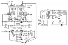
A starting point could be a single ended amplifier based on a triode-pentode tube with noval base such as PCL86. Easy to build, even without a circuit board, does not require expensive transformers and it is compact. A multichannel setup will take less space than other designs with separate preamp and power tubes, it could even be built on a single chassis. Output power will be 3-4W per channel, enough to taste the tube technology. The triode output could be routed to a line out connector, so this amplifier may also be used as a preamp.
If you want to try something simple look here, ~4W out.
No expensive parts and tubes under 5$.And no very high voltages.
I am not in the position to build it myself, disabled and in a home for old people but no doubt other members will check the drawing for errors .
Mona
No expensive parts and tubes under 5$.And no very high voltages.
I am not in the position to build it myself, disabled and in a home for old people
but no doubt other members will check the drawing for errors .Mona
Attachments
Tubes can give "sweet tube sound" or "warm tube sound" if you want effects; they can even do fairly accurate hi-fi sound too, if you want no effects. You need to decide what you want and design accordingly.
Start with something simple, but only believe 50% of what you read online. The snag is that you may not be able to tell which 50% to believe. As a guide, you can believe maybe more than 95% of what GoatGuy says. I say that not because I have read through his post in this thread, but because I know he is generally reliable.
Is there a way to test what kind of sound I like? One of the main parts of building this amp will be to first find someone who can lend me his tube amp, so that I can test what I like. Can I maybe a get a good idea using a "cheap" second hand amp, and try different tubes?
- Status
- This old topic is closed. If you want to reopen this topic, contact a moderator using the "Report Post" button.
- Home
- Amplifiers
- Tubes / Valves
- DIY multi channel tube amp.