Ah ok. Any reason you're taking the feedback from there and not the other side of the OPT? (Not arguing, just wanting to learn)
My implementation was based on Kegger's excellent design and arguments.
See: KT88, (ect) Single ended amp, SEUL | Audiokarma Home Audio Stereo Discussion Forums there is a lot of things and learning.
See: KT88, (ect) Single ended amp, SEUL | Audiokarma Home Audio Stereo Discussion Forums there is a lot of things and learning.
jounito,
There are no limits to Creative Genius. Beautiful! What more can I say?
Other than the volume control knobs, are the metal objects on the front bias pots?
There are no limits to Creative Genius. Beautiful! What more can I say?
Other than the volume control knobs, are the metal objects on the front bias pots?
Last edited:
6A3sUMMER,
I posted the schematics again in post #38. The figure in #10 does not work for some reason any more.
The knobs in front are a volume pot (right) and a input selector (left). I have three inputs, seen in figure in post #36. The small "objects" are fastening bolts for the wooden front panel.
I posted the schematics again in post #38. The figure in #10 does not work for some reason any more.
The knobs in front are a volume pot (right) and a input selector (left). I have three inputs, seen in figure in post #36. The small "objects" are fastening bolts for the wooden front panel.
There will not be much NFB, the 220K resistor is driving back into the triode connected 6EJ7. That kind of FB is commonly used feeding back into a pentode, where it can be very effective in lowering the output impedance of the amplifier..🙂
Lower impedance results in better control of the speaker. The amp as is will have a DF in the range of 1-3. Easy to measure, just need a DVM & a load resistor. In the tube era of the 50s, DF of 10 was often the target.
Lower impedance results in better control of the speaker. The amp as is will have a DF in the range of 1-3. Easy to measure, just need a DVM & a load resistor. In the tube era of the 50s, DF of 10 was often the target.
My implementation was based on Kegger's excellent design and arguments.
See: KT88, (ect) Single ended amp, SEUL | Audiokarma Home Audio Stereo Discussion Forums there is a lot of things and learning.
Thanks jounito - great link!
Easy to measure the degree of NFB, with a suitable load resister connected measure the gain with & without the 220K resister connected. The ratio is an indication of the NFB.🙂
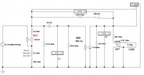
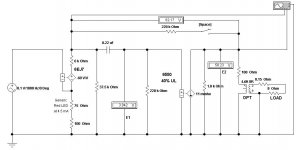
NFB Solution for the 6EJ7/KT88 SEUL Amp
For the curious & others here are the results of a simulation using Electronics Workbench software. The PC Space Bar has been assigned to a switch used to connect or disconnect the 220K FB resister between the 6EJ7 & 6550. The 6550 is enough similar to the KT88 so that the calcs are essentially correct. The NFB appears to be about 5 db, very reasonable for this circuit.
The 6EJ7 data sheet shews MU of 60. Page 2 shews the G to be 8-10 Ma/V with 4.5 mA plate current. That calcs to rp ~6K. So the voltage controlled voltage source is set at -60 V/V. The minus sign is required, this stage inverts.
The 6550 data sheet p5 includes plate curves for 40% UL connexion. The 6550 appears as a voltage controlled current source. From the curves the rp is ~1.8K. The G is 11 mA/V.
The OPT primary & secondary resistances are a best guess from previous experience, but will have negligible effect on the NFB.
There is no DC in this kind of simulation, the LED will not conduct. From previous work I found the incremental resistance of a common red LED to be ~75R at 4.5 mA.
Taking the readings on voltmeter E2-
NFB Disconnected 58.23V
NFB Connected 32.45
20 log 58.23/32.45 Looks like 5.08 db🙂
Attachments
- Status
- Not open for further replies.
- Home
- Amplifiers
- Tubes / Valves
- DIY KT88 SEUL