I have built myself a simple hFE tester with a somewhat elevated collector current, compared to the usual suspects (Multimeter, Peak DCA75, etc. running only a couple milliamps). It is basically just a proof of concept for a more elaborate kind of curve tracer that's still in the making, and not a complete "DIY kit", but I thought I'd share it anyhow. It is not difficult to build, but you'll have to be able to flash an AVR microcontroller. Feel free to hit me up if I can be of any help.
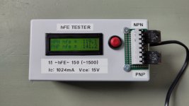
Operation is really simple: put in one or two DUTs (it will hande NPN and PNP at the same time), push the button, and read the result. Easy.
Under the hood, the tester will pull a current of 1024mA (adjustable for calibration) through the emitter for roughly 50µs, sample the voltage drop over a 16 Ohm base resistor (adjustable to trim out tolerances), calculate the resulting hFE and finally display it. The short duration of the current pulse will make sure that the DUT doesn't heat up during testing and thus result in a stable and repeatable result on the display. In fact I can mash the button a dozen times in quick succession and the result will only be off by a single ADC count occasionally, but most of the time it will be spot on. Of course the precision and resolution of the AVR-internal ADC and Vref are limited, and the calculation does not compensate for the base current (so technically it is 1024mA Ie and not Ic), but for picking the best devices from a stash of output transistors it should be good enough.

This is what the operation looks like on the scope. The yellow trace is merely a debug output and something for the scope to trigger on. The first blip shows when the current source is activated for 30µs. On the second blip the CCS gets deactivated and the acquisition of the ADC is started - Sample and Hold takes place just a couple of µs after this, but the ADC conversion takes all the time until the third blip. The cyan trace shows the emitter voltage. As you can see it takes about 15µs after switching on the current source until anything happens there, and the current will keep flowing for another ~30µs after the CCS has been disabled. No need to keep the current active through the full acquisition cycle and cause additional dissipation in the DUT!

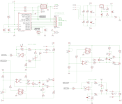
The schematic. Nothing overly special here, all jellybean parts. The TL431 with its 2.5V was deliberately chosen as the Vref for the current sources. Since that voltage sits close to the rails, the input common mode range of the opamp has to be up for the task. Using something <=100mV here would have necessitated the use of a rail-to-rail opamp. While the TL074 is actually up for this job on the positive rail only, I'd have to use something like an LM324 for the negative rail. I wanted to make do with a single quad opamp from the parts bin though, so I chose the higher Vref for its ubiquity in case of the 431 and it being safely inside the CM range of pretty much any opamp you might throw at it. A noteworthy (probable) downside is, that the Vgs-on of the used power MOSFETs has to be greater than these 2.5V, or else the CCS won't fully turn off. Fortunately most of the jellybean power MOSFETs apply here, so don't use any fancy logic-level parts.
There are two sets of four matched 10k resistors. I am not sure if you can get away with some randomly chosen 1% parts here and how severely that would affect precision; I have matched mine to be within 10 Ohms each. The whole circuit around the diff-amps might even be simplified, but originally I had intended to use some other voltage than ground to reference them to. That didn't work out as intended though, so I left it that way.


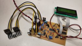
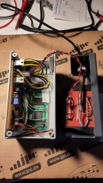
Some photos of my device. Got a little cramped inside the case, but everything fit in. The transformer has two 9V secondaries and existed for half an eternity in my parts bin. The circuit was actually tailored around this thing, exploiting the fact that the raw rectified DC sits somewhere around 14V and thus is safe to use without any further regulator on the analog part (5V for the µC being mandatory of course). This limits the Vce to that same ~14V; increasing it would have made the whole circuit much more complicated. The transformer doesn't have to supply lots of current, as there's no sustained high current demand from the tester.
The ZIP file contains the controller source code, written in assembler, and the compiled HEX file ready to flash. Again, if you want to build this and need any help or advice, feel free to ask me.
Operation is really simple: put in one or two DUTs (it will hande NPN and PNP at the same time), push the button, and read the result. Easy.
Under the hood, the tester will pull a current of 1024mA (adjustable for calibration) through the emitter for roughly 50µs, sample the voltage drop over a 16 Ohm base resistor (adjustable to trim out tolerances), calculate the resulting hFE and finally display it. The short duration of the current pulse will make sure that the DUT doesn't heat up during testing and thus result in a stable and repeatable result on the display. In fact I can mash the button a dozen times in quick succession and the result will only be off by a single ADC count occasionally, but most of the time it will be spot on. Of course the precision and resolution of the AVR-internal ADC and Vref are limited, and the calculation does not compensate for the base current (so technically it is 1024mA Ie and not Ic), but for picking the best devices from a stash of output transistors it should be good enough.
This is what the operation looks like on the scope. The yellow trace is merely a debug output and something for the scope to trigger on. The first blip shows when the current source is activated for 30µs. On the second blip the CCS gets deactivated and the acquisition of the ADC is started - Sample and Hold takes place just a couple of µs after this, but the ADC conversion takes all the time until the third blip. The cyan trace shows the emitter voltage. As you can see it takes about 15µs after switching on the current source until anything happens there, and the current will keep flowing for another ~30µs after the CCS has been disabled. No need to keep the current active through the full acquisition cycle and cause additional dissipation in the DUT!

The schematic. Nothing overly special here, all jellybean parts. The TL431 with its 2.5V was deliberately chosen as the Vref for the current sources. Since that voltage sits close to the rails, the input common mode range of the opamp has to be up for the task. Using something <=100mV here would have necessitated the use of a rail-to-rail opamp. While the TL074 is actually up for this job on the positive rail only, I'd have to use something like an LM324 for the negative rail. I wanted to make do with a single quad opamp from the parts bin though, so I chose the higher Vref for its ubiquity in case of the 431 and it being safely inside the CM range of pretty much any opamp you might throw at it. A noteworthy (probable) downside is, that the Vgs-on of the used power MOSFETs has to be greater than these 2.5V, or else the CCS won't fully turn off. Fortunately most of the jellybean power MOSFETs apply here, so don't use any fancy logic-level parts.
There are two sets of four matched 10k resistors. I am not sure if you can get away with some randomly chosen 1% parts here and how severely that would affect precision; I have matched mine to be within 10 Ohms each. The whole circuit around the diff-amps might even be simplified, but originally I had intended to use some other voltage than ground to reference them to. That didn't work out as intended though, so I left it that way.


Some photos of my device. Got a little cramped inside the case, but everything fit in. The transformer has two 9V secondaries and existed for half an eternity in my parts bin. The circuit was actually tailored around this thing, exploiting the fact that the raw rectified DC sits somewhere around 14V and thus is safe to use without any further regulator on the analog part (5V for the µC being mandatory of course). This limits the Vce to that same ~14V; increasing it would have made the whole circuit much more complicated. The transformer doesn't have to supply lots of current, as there's no sustained high current demand from the tester.
The ZIP file contains the controller source code, written in assembler, and the compiled HEX file ready to flash. Again, if you want to build this and need any help or advice, feel free to ask me.