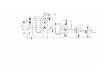
Simple amp. based on SG3525 PWM IC.
Frequency is fixed to 150kHz (fixed f is good choice) but you can modify it by changing RT/CT.
PWM is ~2-98% (which is very good).
IR2184 is HI/LO side gate driver.
Dead time provided by this IC.
Set the potentiometer on half.Turn amp ON.Set output voltage to 0V.
This amp works from first attempt 😉
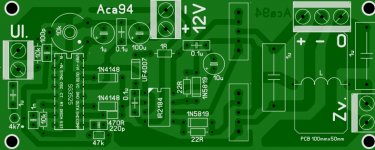
On PCB i have to use external 12V PSU for IC's
Max input voltage is +-80V.
With 4k7 adjust gain.
Output inductor is gapped core (can be used yelow toroids from AT/ATX PSU,they have internal gap.
In external 12V version you can regulate the output power only by voltage on fets.
12V is referenced to -V,not to GND!
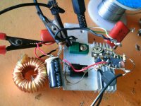
On picture I used totem pole output instead of FET's and driver IC,but I tested wih IC and FET's too.
Frequency is fixed to 150kHz (fixed f is good choice) but you can modify it by changing RT/CT.
PWM is ~2-98% (which is very good).
IR2184 is HI/LO side gate driver.
Dead time provided by this IC.
Set the potentiometer on half.Turn amp ON.Set output voltage to 0V.
This amp works from first attempt 😉
On PCB i have to use external 12V PSU for IC's
Max input voltage is +-80V.
With 4k7 adjust gain.
Output inductor is gapped core (can be used yelow toroids from AT/ATX PSU,they have internal gap.
In external 12V version you can regulate the output power only by voltage on fets.
12V is referenced to -V,not to GND!
On picture I used totem pole output instead of FET's and driver IC,but I tested wih IC and FET's too.
Attachments


Better use TL494 in place of SG5325 with collectors joined 'ORed' and you will get better results. Try to use feedback also to make it immune to gain variation with power supply deviation.
@airwavesystem
It's better than UcD
@workhorse
No,I tried it,and here's more noise than 3525.And max. PWM on 494 is smaller.
I want to have no feedback.Because of this power can be varied only by voltage on fets,without any change.You can use variable supply and vary volume by it.
@Freeman
Yes.
@chinokscapsighter
Thank you.
Few man's from another forum make this amp. in progress.
When they make it,I'll post here.
Last edited:
just a few questions from Holland......
Can I use the IR2117 to replace the IR2184?
Which transistor can i use for T3
Must R13 be 4K for 80V
Which Fets are T1 and T2 and can I put for example 2 X IRFP460 into your design and bring up the supply to 150V?
Thanks for looking at my questions.
Hank
Can I use the IR2117 to replace the IR2184?
Which transistor can i use for T3
Must R13 be 4K for 80V
Which Fets are T1 and T2 and can I put for example 2 X IRFP460 into your design and bring up the supply to 150V?
Thanks for looking at my questions.
Hank
hi acca this a very nice project . just wanted to know have you tried your amp at +/-80vlts with 1ohm load? which fets did you use .? and can it be bridged at 2ohms with that voltage?
also can i redraw your schema and use ir2110 or ir2153 as the gate drivers.?
thanking you in advance steve .
also can i redraw your schema and use ir2110 or ir2153 as the gate drivers.?
thanking you in advance steve .
just a few questions from Holland......
Can I use the IR2117 to replace the IR2184?
Which transistor can i use for T3
Must R13 be 4K for 80V
Which Fets are T1 and T2 and can I put for example 2 X IRFP460 into your design and bring up the supply to 150V?
Thanks for looking at my questions.
Hank
IR2117 is only one side driver.IR2184 is two side drivers with internal dead time,so my ansver is not.But it can be used with different schematic.
R can be 3k9 2W
Transistor can be darlington for twice voltage than supply,and 3A min.It's better to use external psu,but not more than 15V! Over it IR2184 blow up.
If use transformer it must have voltage on secondary 9-10V.
Yes,you can but look out for high current lines!
Last edited:
First sory for late answer,there's no new mail from this forum and I dont think about this.hi acca this a very nice project . just wanted to know have you tried your amp at +/-80vlts with 1ohm load? which fets did you use .? and can it be bridged at 2ohms with that voltage?
also can i redraw your schema and use ir2110 or ir2153 as the gate drivers.?
thanking you in advance steve .
Tried with +-40 on 0.5R load,which is same.lights in my house blinks with music 😀
Fets should use with smallest gate charge what you find.
I dont know can be IR2153 used for this.
IR2110 can be used,but one input must be 180' out of phase than other.
THERE'S MISTAKE ON PCB!
Pin1 and pin2 on SG3525 must been swaped.Pin 1 goes to pin 2 on pcb and pin 2 goes to pin 1 on pcb.
Pin1 and pin2 on SG3525 must been swaped.Pin 1 goes to pin 2 on pcb and pin 2 goes to pin 1 on pcb.
First sory for late answer,there's no new mail from this forum and I dont think about this.
Tried with +-40 on 0.5R load,which is same.lights in my house blinks with music 😀
Fets should use with smallest gate charge what you find.
I dont know can be IR2153 used for this.
IR2110 can be used,but one input must be 180' out of phase than other.
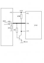
hi acca thanks for the reply please post a simple schematic to guide me with ir2110 i want to make this amazing amp
Ok,here's it.You can use inverter IC instead of transistor.I ask my friend can be ir2153 used for this.
Attachments
Last edited:

Hi Acca what type of IR2184 are you using on this design?i can't identify the pin configuration,thank's.
- Status
- Not open for further replies.
- Home
- Amplifiers
- Class D
- DIY Good Class D amplifier