I think there was a mention about using this stage directly after the ZenMod Iron Pre that uses the Jensen/Cinemag line transformer - perhaps it might depend on the characteristics of your dac's o/p transformer too
I tested it, and works very well without C1 and C2 after my Sowter DAC transformer.
I think my DAC never sounded as beautiful as now. Thanks
I think my DAC never sounded as beautiful as now. Thanks
Excellent, and all the 'buzz' of successful diy - there's just something about a transformer in the signal path ...
Question about this front end kit when using a 48v Single V+ switching PSU.
I am getting a high pitch squealing sound with the larger 48V, but when using 19V and 24V the unit is dead quiet. Tried 3 different 48V Meanwell supplies and each one squeals.
I have R13 stuffed. Could that be what is causing the issue with the 48V wart?
The preamp is powering Amp Camp monoblocks at 5db of gain. Is it even necessary to get the larger 48V PSU?
Any help is appreciated!
I am getting a high pitch squealing sound with the larger 48V, but when using 19V and 24V the unit is dead quiet. Tried 3 different 48V Meanwell supplies and each one squeals.
I have R13 stuffed. Could that be what is causing the issue with the 48V wart?
- R13 stuffed
- R10 is jumpered
- V- being used as ground jumped to -in
- VG is not being used
- I am not using Marks SMPS filter
The preamp is powering Amp Camp monoblocks at 5db of gain. Is it even necessary to get the larger 48V PSU?
Any help is appreciated!
Pictures are always welcome and may help in trouble shooting.
Were C6 and R14 omitted?
DIY FE with 5dB of gain - what resistor changes did you make?
Amp Camp Amplifier does not need high voltage input signal (has 14dB gain (5X) and 5W output) so 48VDC power supply is not necessary for the DIY FE.
Were C6 and R14 omitted?
DIY FE with 5dB of gain - what resistor changes did you make?
Amp Camp Amplifier does not need high voltage input signal (has 14dB gain (5X) and 5W output) so 48VDC power supply is not necessary for the DIY FE.
Hi guys, I'm trying to build this circuit. Could it be useful, once done, to measure the DC offset? If yes, how should this test be performed? Keep in mind that I will feed it with a SE PSU @24VDC.
Thanks to all,
Gaetano.
Thanks to all,
Gaetano.
With the output capacitor there should be no measurable offset at the output when connected to an amplifier. There may be some offset at power-up but that should dissipate quickly.
However if you measure with no amplifier or dummy load attached, an offset may be measured at the output, but that is to be expected with this circuit.
There is no danger to the connected amplifier.
If the DIY FE is used as a stand alone preamp always power up the FE first, then the amplifier, to avoid any pops.
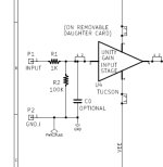
Yes. C6 and R14 both omitted but I stuffed R13 with a resistor. I snapped this pic before finishing.Pictures are always welcome and may help in trouble shooting.
Were C6 and R14 omitted?
DIY FE with 5dB of gain - what resistor changes did you make?
Amp Camp Amplifier does not need high voltage input signal (has 14dB gain (5X) and 5W output) so 48VDC power supply is not necessary for the DIY FE.
I can take a new one tomorrow. But knowing a 48V is overkill maybe 24V is the way to go?
Attachments


Somebody is either breaking down or oscillating at the higher voltage.
Try using the compensation cap on the 2nd stage. If that doesn't do it, try replacing the P or N channel devices on the output stage. Also (easier) load the output with some resistance to ground.
And see what you get.
Try using the compensation cap on the 2nd stage. If that doesn't do it, try replacing the P or N channel devices on the output stage. Also (easier) load the output with some resistance to ground.
And see what you get.
I started with +12dB (which is R3 & R4 = 40kohm) on my MoFo. I like to socket things until I settle on a permanent value,
When I'm happy with the value, I remove the socket then solder in permanently.
BTW, these are my own PCBs with Texas Instruments JFE2140 as the long tailed pair. Can also use LSK389 SOIC or TO-71.
I got a little impatient waiting for boards to be stocked in The Store.
View attachment 1186813


Thank you cinco for the files!
It's probably the only time where I have all the parts ready for anything 🤣
Now I can finally put the JFEs to good use
(Also, thank you Pa for the great work)
Thank you for the recommendation here. I ended up sticking with a 24V PSU and no issues there!Somebody is either breaking down or oscillating at the higher voltage.
Try using the compensation cap on the 2nd stage. If that doesn't do it, try replacing the P or N channel devices on the output stage. Also (easier) load the output with some resistance to ground.
And see what you get.
If I go up to 48V in the future I will try the compensation cap.
Has anyone took Mark’s advice and used the front end as an input for the m2x (as the daughter board). I would use the boards from the store.
I’m thinking of trying it but a couple questions.
- to power the FE boards, should I take the the V- and V+ to the Pin 1 and 3 M2X posts or direct from the psu board?
- for Pins 2 and 4, can I take the output of the FE directly into Pin 4? This would bypass CO, R1 and R2, correct?
- what gain would be recommended? I was thinking 5 db or 10 db.
Thanks!
Attachments
Re. gain: the other option is to employ the fe2022 as the sole gain device and omit the edcor trafo completely.
Of course some people will say it's no longer an M2x, but to me the main feature of M2x is the total lack of NFB, local or otherwise.
With fe2022 in place you are introducing FB at least to a portion of the amp and that will definitely make it sound different, not necessarily better or worse, just different.
Thanks for the feedback.
Would it be better to just add the FE in front of the m2x while using daughter boards?
One reason of doing this is to be able to add the balanced input.
Would it be better to just add the FE in front of the m2x while using daughter boards?
One reason of doing this is to be able to add the balanced input.
Does it make sense to create a sub class of FE and OP? For mixing and matching?
Put them in separate boxes with cables in between. Perhaps a shared ground wire too?
Put them in separate boxes with cables in between. Perhaps a shared ground wire too?
It makes lots of sense. I have several upcoming projects that approach it in this manner, the attraction being that you can play with these components individually, just as you might mix amps and preamps.
Hello Dneu2011,
I am going to use the FE2022 together with the ZD25 MINI (aka 'The Holy Grail Follower) Ihquam made. This is the outputstage from the M2X (with optocoupler...) but directly driven by an opamp or another frontend (no transformer).
My railvoltages became higher than expected (+-32 V DC), so I have to check how the FE2022 likes that.
Although Nelson Pass meant, that he was driving it up to 70 V - if I remember right? I think 70 V DC in single ended or +-35 V DC ?
Perhaps I will try a cascoded frontend?
Cheers
Dirk
- Home
- Amplifiers
- Pass Labs
- DIY Front End 2022