Peter Walker, Founder of Quad, discovered an interesting
(teoretical) law of physics:
Regardless of Esl size or membran/stator distance, the Esl
will produce 100 db when the signal current to the stators
is 5 milliampere.
This is a very useful rule to keep in mind, I think!
Jonas
(teoretical) law of physics:
Regardless of Esl size or membran/stator distance, the Esl
will produce 100 db when the signal current to the stators
is 5 milliampere.
This is a very useful rule to keep in mind, I think!
Jonas
Interesting. I suspect some context is missing here. Can you cite where you saw this and exactly what Walker did say?
doubts
Hi,
I doubt the correctness of this 5ma-ruleofthumb.
The frequency resonse of an ESL is relatively linear when driven with a constant voltage. Driving with a constant 5ma current would mean to have an voltage increase of 6dB/oct with falling freqs, or vice versa a falling acoustical response with increasing freqs. The rule might aplly to a certain ´center frequency´ but not to the complete audio spectrum.
jauu
Calvin
Yes, Calvin is right. I’m sure that whatever Walker said was right; I just think we’re missing some assumptions that he must have made. I think the germ of the idea comes from this comparison:
Case 1: Stators are 2mm apart, arbitrarily. Drive voltage across stators is Vss. Stator-to-stator capacitance is Css. Arbitrary driving frequency is f. Current through stators is thus Iss = Vss*2*pi*f*Css. Charge on diaphragm is Q. Near-field SPL measurement is X dB SPL.
Case 2: Stators are pulled apart to 4mm. Capacitance is halved. To maintain same SPL drive voltage must be doubled to 2Vss. Q on diaphragm must remain constant by doubling polarizing voltage, because Q=VC. Iss stays the SAME for the SAME SPL in the second case as in the first case, because Vss is doubled, while capacitance is halved.
But frequency and charge are variables that must be held constant to make this comparison work. Stator size (area) would also affect capacitance and therefore current, but in the NEAR-FIELD won’t affect observed SPL as long as the stator dimensions are much larger than the observation distance. My thoughts on it, anyway…
It was many years ago, Peter Walker was on a promotion
tour in Sweden, demostrating his then new Esl 63 speaker
at "Rosens Ljudcenter" in Malmoe.
He tried to explain the signal delay circuitry for us normal
beings in easy to grasp terms, when he mentioned the
little rule, 5 mA = 100 db.
I've also red it somewhere at the Internet, can't remember
where, shall see if I can find it.
Jonas
Not to belabor this question, but I find this interesting:
So Walker was describing his ESL-63 (my own speaker). Here’s some speculation about what he might have meant relative to that design:
The delay circuitry also acts as a string of low pass filters, so that each larger ring around the “bull’s eye” outputs less and less high frequencies. This is easily observed if you remove the grills of the 63s (revealing high-voltages – careful) and use a non-conductive tube, perhaps a paper towel cardboard tube as a stethoscope. Hold one end to your ear and the other close to the stator grid. At the center, you will hear full range sound (with lots of highs). As you move the tube outward, each successive annular ring will sound duller and duller.
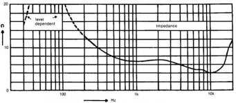
So, at 20 kHz, only the center spot (“bull’s eye”) receives audio voltage, at 2 kHz several rings produce output, and at 200Hz, nearly the entire speaker’s surface is in play. For a fixed audio drive voltage at 20kHz, 2kHz and 200Hz, the audio current will be roughly (very roughly!) constant, since the effective area of the stator “seen” by each frequency is inversely scaled, as is the capacitance. In effect, the delay line filter help to keep the impedance more constant across the frequency band, unlike a pure capacitive ESL. Actual impedance curves of the ESL-63 are hardly flat, but they are flatter across the mid band than a pure capacitor would have been. Look between 300Hz and 10kHz. The impedance varies from 10 ohms to 4 ohms. A 33:1 frequency span results in a 2.5:1 impedance range. This is 13 times flatter than the impedance curve of a capacitor. Probably somewhere in this frequency range 5mA in the stator corresponds to 100dB SPL (at some unspecified distance).
So Walker was describing his ESL-63 (my own speaker). Here’s some speculation about what he might have meant relative to that design:
The delay circuitry also acts as a string of low pass filters, so that each larger ring around the “bull’s eye” outputs less and less high frequencies. This is easily observed if you remove the grills of the 63s (revealing high-voltages – careful) and use a non-conductive tube, perhaps a paper towel cardboard tube as a stethoscope. Hold one end to your ear and the other close to the stator grid. At the center, you will hear full range sound (with lots of highs). As you move the tube outward, each successive annular ring will sound duller and duller.
So, at 20 kHz, only the center spot (“bull’s eye”) receives audio voltage, at 2 kHz several rings produce output, and at 200Hz, nearly the entire speaker’s surface is in play. For a fixed audio drive voltage at 20kHz, 2kHz and 200Hz, the audio current will be roughly (very roughly!) constant, since the effective area of the stator “seen” by each frequency is inversely scaled, as is the capacitance. In effect, the delay line filter help to keep the impedance more constant across the frequency band, unlike a pure capacitive ESL. Actual impedance curves of the ESL-63 are hardly flat, but they are flatter across the mid band than a pure capacitor would have been. Look between 300Hz and 10kHz. The impedance varies from 10 ohms to 4 ohms. A 33:1 frequency span results in a 2.5:1 impedance range. This is 13 times flatter than the impedance curve of a capacitor. Probably somewhere in this frequency range 5mA in the stator corresponds to 100dB SPL (at some unspecified distance).
Attachments
I've found the Peter Walker article:
http://www.quadesl.org/aes633.gif
Not so easy to read, scanned copy of copy of......
Jonas
http://www.quadesl.org/aes633.gif
Not so easy to read, scanned copy of copy of......
Jonas
SillyCone,
Thanks for posting that article. I remember reading it a long time ago, but I didn’t retain a copy until now. It seems to be a speech that has been captured, and is not very easy to follow. His formula for sound pressure IS dependent upon stator spacing, d, polarizing voltage, E, and distance to the observer, r. But as you say, it is independent of panel size and frequency. Compared to my thoughts above, where I assumed near-field measurements, he assumed far-field measurements (the 1/r term). In his case, if one doubles the area of the panels while keeping the stator current a constant (which requires halving the drive voltage) the result is no change in sound pressure. That part seems almost obvious. The frequency independence is harder to grasp, but I think there is a clue in the paragraphs following the formula, where he describes tuning out the stator-to-stator capacitance with a bridge. I think that the constant current he keeps referring to must be only that current that flows into the radiation resistance leg of the ESL equivalent circuit, and not into the capacitance portion. This is a very interesting relationship, but may be tough to relate to real-world measurements by DIY’ers. It is too easy to assume that an ESL’s impedance is purely capacitive since often the capacitive part does dominate, but in order for the speaker to radiate energy as sound pressure there has to be resistive part to the impedance that represents the acoustic radiation resistance loading on the diaphragm. It’s that little bit that does all the work, and this is why ESLs have been labeled as extremely power efficient, but not necessary as very sensitive, since a lot of reactive current is wasted in the capacitive part.
Anybody else have an interpretation of Walker’s words?
This turned out to be an intersting thread!
Ok, according to the formula the esl is dependant on stator spacing
and biasvoltage, but if you substitute these 2 factors with a constant
field strengt of, lets say 2E6volt/meter, then the only variants
are current and distance to the speaker. If we keep the distance to
the (europe) standard of one meter. we have only the current to deal with.
This must be interesting to all the Diy:ers who have built Esl:s with
resistor segmented stators, because if You try to limit the frequency
to 5 KHz at the stator strip adjacent to the full bandwidth strip, you
can never get the same current flow as to the full bandwidth strip,
thus never a smooth frequency responce.
Coils are obviously much more suited here! (Quad!)
Jonas
Hi SillyCone,
the current of an ESL is proportional to its capacity. So if you doubt the performance of segmented stators you need to consider that each segment means a specific capacity depending of its area. By selecting the right size of each segment (mostly just the width), you can fulfill the criteria of same current in each segment. I can tell you that my segmented panels show a very flat frequnecy response. I never designed my panels regarding the current theory, even i doubt it to be practible. But it is possible that my trial and error method (supported by lots of measurements) of finding the best segmenting, results in same current of each segment.
The coils in the Quad speakers have nothing to do with the"current theory", its just the segmenting. The coils show a very high inductance , enabling a slightly response delay from segment to segment. Such a delay line is very complex and can't be realized perfectly if made with passive components. But if you watch the step response of the quads, walker did a great job to come real close.
capaciti
Hello Capaciti,
No doubt, You can absolutely design a flat response EsL with
resistor segmenting.
The current to a Esl is depending on its capacity, the frequency of
the current and the voltage applied to stator.
If You want the same current flow to an adjacent strip as to the full bandwidth (center) strip (that in most cases has no resistor in series), You have to make the adjacent strip undesirable wide according to my (incorrect?) calculations.
Of course, you can put a resistor to the center strip also, but then
we risk to loose the famous top frequencies of the Esl.
The only thing I want, is to say that we DIY:ers maybe can use
Walkers rule when we design our loudspeakers.
For one thing, it seems that You can measure the actual frequency
response of an Esl just by measuring the current flow to one
of the stators at selected frequencies.
Jonas
For one thing, it seems that You can measure the actual frequency response of an Esl just by measuring the current flow to one of the stators at selected frequencies.
I wish it could be that easy, but as I said above, that is not what I think that Walker was trying to explain, in my interpretation anyway. If you held voltage constant as you swept the frequency (a normal thing to do), and measured the resultant current (either at a stator or as transformed to the primary of the step-up transformer) you would simply be deriving a curve corresponding to the impedance (or more properly admittance) of the ESL (V divided by I). Take a look at the ESL-63 impedance curve that I showed above and compare it to the same speaker’s relatively flat frequency response (in Walker’s paper). The impedance of the ESL does not correspond directly to the acoustic response, because of the relatively large shunt capacitance which will suck in “wasted” current that has nothing to do with the current through the radiation resistance and the force on air (even with the ESL-63 being flatter in impedance than most ESLs). In this paper, Walker showed how to make a bridge circuit to tune out the constant capacitance component to arrive at just the current through the radiation resistance. The only plausible alternative view is that as the capacitance draws in more current at higher frequencies, so does the ESL become more beamy on axis and the response rises roughly in accordance with the rising current. This does not correspond however to the ESL’s power response in the room, only to the on-boresight response. The capturing of Walker’s words is not so definitive to be sure, but I think he was saying that you have to tune out the wasted capacitive current first. You could use a bridge, or just remove the current later by a math calculation at each frequency, if you already know the capacitance, perhaps by using a spreadsheet. I am really open to alternate views on Walker’s paper, however.
I shall go deeper with this "Walker rule" to see what is
or is not possible to do with it!
Thanks to You All!
Jonas
or is not possible to do with it!
Thanks to You All!
Jonas
Member
Joined 2003
I have a pair of Martin Logan electrostats and they play for me more than my neighbours approve of. I have no problems with "low" maximum sound level.
Hi,
I built a a simple jig..kind of a frame with moveable bowed sections at top and bottom.
I used as much tension as the film could stand. My 3.5µm Film reaches a resonance of app. 150-170Hz. You may go higher with thicker and stronger film (250Hz w. 12µm as ML does), but even though You get a perfect amplitude response using a HP 2nd order down to the resonance, I prefer to have a cutoff of min. double the resonance. ML does it this way, but I´m convinced that the sonic footprint of the resonance (long decay) is audible. Too a thinner, lighter membrane sounds more open and detailed than a thick one.
jauu
Calvin
Hi,
I see you have lots of experience with ESLs 🙂.
So , my question is , what can be the reasons that a DIY ESL sounds "harsh" ? did anybody else have this problem ?
I have come up with a few possibilities :
1. Wrong type of diapraghm film ;
2. Not equal tension of film or varying stator capacitance ;
3. Problems with electronics(amplifier , etc ..) ??
Thanks in advance ,
Lukas.
Could it be the uncorrected beaming response of a panel at higher frequencies?
Or an unhappy amplifier?
A good ESL is anything but harsh, IMO.
Or an unhappy amplifier?
A good ESL is anything but harsh, IMO.
Hi,
Maybe it can be uncorrected beaming.. You mean , i have to add a series resistance to decrese this ? .I tried to play some tones via tone generator ; it is hard to tell something accurately without a mic.
I was wondering how the sound quality is related with constrution accuracy(like spacer thickness tolerance , etc..) ?
In fact , i am using a simple DD amp , with a few hundred volts RMS output for testing. maybe it is the problem with it . Probably the only way to test is to try a good tube output trannie , which i have yet to find..
Regards,
Lukas.
SCREAM part iV 🙂
Hi,
the reason for harsh sound is in nearly all cases grounded in the frequency response. ESLs tend to have elevated mid-highs(1-4kHz). Speakers tend to ´scream´ with female voices and big choirs when this frequency range is too dominant. On the other hand a pronounced area around 1kHz gives the speaker ´speed´and ´livelyness´. Differences of as little as 0,5dB in this freq-range can change the character of the speaker. You can counter the ´screaming-effect´a bit with a small dip around 4kHz. So You might have to work with equalization.
The second reason can be elevated highs because of resonance. The trannies stray inductance and the speakers capacity form a resonant circuit. If this resonance lies within the audible range and isn´t dealt with with a damping resistor You´ll have a rising freq-response at the top end. Since commercial manufacturer have an eye on costs, they often use cheap and bad trannies with a resulting resonance as low as 10kHz(!) with damping resistors or even more complicated equalization. Better is to use good trannies giving enough bandwidth and to cope with the (ultrasonic) resonance with just a small resistor. Too this resistor loweres the SPL towards higher freqs. So You can fudge with this resistor to get the desired sound balance.
jauu
Calvin
Hi,
the reason for harsh sound is in nearly all cases grounded in the frequency response. ESLs tend to have elevated mid-highs(1-4kHz). Speakers tend to ´scream´ with female voices and big choirs when this frequency range is too dominant. On the other hand a pronounced area around 1kHz gives the speaker ´speed´and ´livelyness´. Differences of as little as 0,5dB in this freq-range can change the character of the speaker. You can counter the ´screaming-effect´a bit with a small dip around 4kHz. So You might have to work with equalization.
The second reason can be elevated highs because of resonance. The trannies stray inductance and the speakers capacity form a resonant circuit. If this resonance lies within the audible range and isn´t dealt with with a damping resistor You´ll have a rising freq-response at the top end. Since commercial manufacturer have an eye on costs, they often use cheap and bad trannies with a resulting resonance as low as 10kHz(!) with damping resistors or even more complicated equalization. Better is to use good trannies giving enough bandwidth and to cope with the (ultrasonic) resonance with just a small resistor. Too this resistor loweres the SPL towards higher freqs. So You can fudge with this resistor to get the desired sound balance.
jauu
Calvin
- Status
- Not open for further replies.
- Home
- Loudspeakers
- Planars & Exotics
- DIY Electrostatic - maximum safe db ?