http://sound.westhost.com/project105.htm
This site hasn’t changed for 1- 2 years. Anyone built this ~ did it get off the ground?
The best component DIY Electrostatic souce seems to be ER Audio at www.eraudio.com.au/Components/components.html
I’m hoping for 105-110 db from ESLs from about 500 Hz up - who knows the maximum db you can safely get from them?
Cheers
As always, it depends! There is no fundamental practical limit to the maximum SPL of ESLs any more so than with moving coil speakers. It depends on ESL size, panel configuration, stator-to-stator spacing, etc. Limiting use to above 500Hz will lower excursion of the diaphragm and reduce the risk of the diaphragm hitting a stator, just as limiting bass in a moving coil driver reduces risk of reaching Xmax displacement. It would be quite possible to make a deafening (literally) large ESL. The big Sound Labs ESLs, with enough driving juice, can pin your ears back at 10 paces. If you were asking specifically about the maximum SPL of ER Audio kit speakers, someone else would have to say.
SPLmax
Hi,
above app. 200Hz the needed excursion for high volume levels is quite small and there is no reason, why an ESL shouldn´t reach similar SPLs as any dynamic driver. In fact an ESL has two distinct advantages over the dynamic driver. First is a greater diaphragm area -not necessarily, but in most cases- Since SPL is a function of area and excursion an ESL can reach higher SPLs (btw. shows less distortion)
Second is a different behaviour over distance. When built as a long and narrow strip (compared to wavelength) the ESL has a dipolar cylindrical distribution pattern. For a panel of ML´s Sequel size and bigger this means that SPL will rise up to a distance of app. 3-4m and will then start to fall...but with 3dB/doubling of distance...This is theoretically 3db less than with global distribution. So while a dynamic driver will be louder ar close proximity, the strip like ESL can be louder on distance. That makes a comparison a bit difficult.
I measure my panels on different positions. 0.1m (nearfield), 1.0m (standard for dynamic speakers), 2.0m (my standard for ESLs which gives similar results in SPL as 1.0m dynamic measurement) and at the listening position itself in the room.
Crossed over at app 300Hz, I can reach ear chattering SPLs with exceptional clearness. I´m not at all afraid to play Cincinnatti Pops at highest endurable levels. 😀 ...a musical material well known to have fried some boxes
jauu
Calvin
Hi Calvin,
Very good points.
My listening distance will be about 3 m. I’m considering 2 * 930 x 300 a side.
How big are your panels, and what is there design/ material source?
> I measure my panels . . 2 m (my standard for ESLs which gives similar results in SPL as 1 m dynamic measurement) and at the listening position
What max dB do you get, with what amp?
Cheers
Richard
Calvin makes a good point about the distortion of an ESL at loud volumes. Moving-coil cones will gradually produce more and more distortion as they play louder and louder (making them sound louder than they really are), until they are literally crying out distortion. Cones will break up, creating non-linear resonant modes. ESLs, for the most part, enjoy low distortion, since the driving-force electrostatic field is virtually constant anywhere between the stators. ESL distortion will remain very low as the volume is increased until limiting occurs either by arcing or by the diaphragm hitting the stator, neither of which is a good thing. This is a bit reminiscent of a high-feedback amplifier that stays low in distortion until it finally clips.
This one has 123dB at 4 meters, but price is not nice.http://www.sonus.de/php/p_produkte.php?produkt_id=15&work_id=2
Design
Hi,
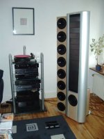
there are some pics of my panels in this forum.
125*25cm 3-4staggered perforated metal coated with a Nylon-derivate powder | 30° arced | 1mm d/s | 3.5µm film highly stretched giving a fs of ~150Hz| own highly transparent coating -and tried Licron with good technical, but lousy optical results 🙄- | toroid transformers 1:76 | simple HV-cascade with just 1700 to 1900V (up to 3kV possible)
Frame is made of special aluminium profiles with a nice curvature.
Bass is a slim tower dipolar design with 8 18cm drivers.
The crossover is made active fc~300Hz (last but not least design)
Amplification of the panel is done with a Rotel RB980BX -I plan to use digi amps in future.
I haven´t measured the SPLmax, but playing music I had to leave the room, because I couldn´t stand it...Eventually the protection of the Rotel switched off, but the panels hadn´t reached their limits then
If You plan to reach high levels of SPL above 300Hz You should consider panel dimensions of ~100*20cm and more. A d/s of 1mm is sufficient. Streching of the diaphragm should be as strong as possible -this leads to a much higher SPLmax because of safety against touching the stators- A lot of DIY-panels suffer from a too low tension (unless You plan a fullrange ESL there is no good reason for low tension i.e. low fs)
jauu
Calvin
Hi,
there are some pics of my panels in this forum.
125*25cm 3-4staggered perforated metal coated with a Nylon-derivate powder | 30° arced | 1mm d/s | 3.5µm film highly stretched giving a fs of ~150Hz| own highly transparent coating -and tried Licron with good technical, but lousy optical results 🙄- | toroid transformers 1:76 | simple HV-cascade with just 1700 to 1900V (up to 3kV possible)
Frame is made of special aluminium profiles with a nice curvature.
Bass is a slim tower dipolar design with 8 18cm drivers.
The crossover is made active fc~300Hz (last but not least design)
Amplification of the panel is done with a Rotel RB980BX -I plan to use digi amps in future.
I haven´t measured the SPLmax, but playing music I had to leave the room, because I couldn´t stand it...Eventually the protection of the Rotel switched off, but the panels hadn´t reached their limits then
If You plan to reach high levels of SPL above 300Hz You should consider panel dimensions of ~100*20cm and more. A d/s of 1mm is sufficient. Streching of the diaphragm should be as strong as possible -this leads to a much higher SPLmax because of safety against touching the stators- A lot of DIY-panels suffer from a too low tension (unless You plan a fullrange ESL there is no good reason for low tension i.e. low fs)
jauu
Calvin
Attachments
Re: Design
PWM is a good thing for high transforming factors (when you have a transformer that can do the switching rate).
Calvin said:I plan to use digi amps in future.
Calvin
PWM is a good thing for high transforming factors (when you have a transformer that can do the switching rate).
Calvin
Your aluminium frame ESLs look way 😎
Is “d/s” the air gap, and what would be the effect of say increasing it to 2 mm?
How do you know when stretching is sufficient?
Cheers
Your aluminium frame ESLs look way 😎
Is “d/s” the air gap, and what would be the effect of say increasing it to 2 mm?
How do you know when stretching is sufficient?
Cheers
Hi,
d/s is the air gap between diaphragm d and stator s.
Increasing the air gap will reduce efficiency quadratically. So the rule must be to keep the airgap as small as possible for good efficiency.
This is a point where a lot of beginners (and not even those!) make their biggest failure in design. A german manufacturer sold a small panel with 4mm d/s. Even with high polarising voltage and high transformation factor the thing was inefficient. A panel of mine of same size but just 1.5mm d/s (still too much) and much lower transformation factor as well as polarising voltage gave 10dB better efficiency.
When You stretch the film the ground resonance goes up until You reach a point where further stretching doesn´t increase fs any more. For most films this point is reached when the film is lengthened app 2%..4%. Applying the highest mechanical tension gives highest stability under working conditions. Together with the smallest possible airgap it leads to highest SPLmax. As very positive sideeffects the needed polarising voltage and driving voltages go down, thereby reducing risk of arcing and the demands on the amplifier
jauu
Calvin
It’s the electric field intensity between stators that creates force on the charged diaphragm. Electric field is measured in volts/meter. If you double the d/s spacing, and keep drive voltages constant, the applied electric field drops by 50%. Force is proportional to applied signal voltage times the value of the fixed charge divided by the stator-to-stator spacing. This relationship is linear in a push-pull constant-charge system and is not quadratic. That’s why modern ESLs have such low distortion. If you can then double the stator drive voltage (twice the turns ratio in the step-up transformer) with the doubled spacing, the electric field intensity will be restored. The diaphragm won’t “see” any difference between the two cases. Of course, there are complications to doubling the drive voltage: breakdown risks increase, transformer performance gets tougher, etc.
Hi,
From your post i understood , that increasing d/s spacing can decrease distortion in some cases.If true , is it related with electrical field uniformity ? I have made some experiments with perforated steel with 5 mm holes and 1 mm d/s spacing.I was dissapointed.Treble did not sound good at all.
Maybe it is related with poor trannie , but have had few tranformers to test.One was from the old quality tube amp.
linear or squared?
Hi,
Brian I think You mixed up two points.
These are the linearity of the drive system of a constant charge ESL and the behaviour of the efficiency versus air gap size.
The error lies in the assumption of a constant charge! While we can indeed assume it to be constant as long as the airgap is constant, it doesn´t apply to the point, when I change the air gap size!
The reason for this is that the capacity changes.
3 Formulas:
1) Capacity C= (k*A)/d
2) Voltage gradient E= U/d
3) exerted Force F~ C*E
together: F~ (k*A)*U/d²
(with k: a constant | A: diaphragm area and constant | d: airgap size| U: polarising voltage
As an example let us compare two panels that only differ in airgap size by a factor of 2.
Doubling the airgap size leads to a halving of the capacity and(!!) a halving of field density. Hence the force and therefore the efficiency is reduced be a factor of 4, i.e quadratically. This can be countered by doubling the polarising voltage (restoring the field density) and doubling the drive voltages or paralleling 2 panels (restoring capacity).
jauuu
Calvin
Calvin,
Yes, I did assume that constant charge on the diaphragm had to be maintained for the comparison. I should have stated my assumption that polarizing voltage has to be increased to maintain constant charge on the diaphragm when the d/s spacing was increased. In effect, the impedance of the ESL can be shifted by playing with the d/s spacing, with all voltages transforming up or down. Your point about the quadratic efficiency change if this is not done is well taken. Happily the quadratic relationship does not affect the transfer function of the audio waveform once the d/s spacing, voltage ratio and charge are fixed.
My point was in response to your point:
There is no reason that this has to be so. There must be secondary factors at play here - perhaps ionization and corona discharge. My own designs recently have concentrated on relatively high d/s spacing and high polarizing voltages (up to 10KV) with high audio voltages (directly driven by RF tubes). With care in the high-voltage considerations of the insulation materials and spacers, larger d/s spacings are possible with comparable efficiency. My point was that you don't have to ONLY make ESLs with small d/s spacings for efficiency, although it is probably easier for the casual DIYer. In my case, I am interested in fairly deep bass production without resorting to moving coil woofers.
To Bazukaz’s point, larger d/s spacings will smooth the small variations in electric field intensity caused by hole-conductor dimensions of the stator, although I don’t think this is a huge problem if care is taken in stator design with any d/s spacing choice. A FEMM simulation can be useful here, although there is little research that I know of about the sonic effects of variations in the electric field. If large holes and conductor dimensions in the stator are coupled with small d/s spacing, there is not only irregularity in the electric field strength across the plane of the diaphragm, but also force vectors are created parallel to the plane of the diaphragm, which is perpendicular to the desired force direction which is normal to this plane. In effect, the diaphragm is stretched and relaxed on a micro-scale repeatedly across its surface. What effect this might have on the background noise floor is unknown.
Yes, I did assume that constant charge on the diaphragm had to be maintained for the comparison. I should have stated my assumption that polarizing voltage has to be increased to maintain constant charge on the diaphragm when the d/s spacing was increased. In effect, the impedance of the ESL can be shifted by playing with the d/s spacing, with all voltages transforming up or down. Your point about the quadratic efficiency change if this is not done is well taken. Happily the quadratic relationship does not affect the transfer function of the audio waveform once the d/s spacing, voltage ratio and charge are fixed.
My point was in response to your point:
Even with high polarising voltage and high transformation factor the thing was inefficient.
There is no reason that this has to be so. There must be secondary factors at play here - perhaps ionization and corona discharge. My own designs recently have concentrated on relatively high d/s spacing and high polarizing voltages (up to 10KV) with high audio voltages (directly driven by RF tubes). With care in the high-voltage considerations of the insulation materials and spacers, larger d/s spacings are possible with comparable efficiency. My point was that you don't have to ONLY make ESLs with small d/s spacings for efficiency, although it is probably easier for the casual DIYer. In my case, I am interested in fairly deep bass production without resorting to moving coil woofers.
To Bazukaz’s point, larger d/s spacings will smooth the small variations in electric field intensity caused by hole-conductor dimensions of the stator, although I don’t think this is a huge problem if care is taken in stator design with any d/s spacing choice. A FEMM simulation can be useful here, although there is little research that I know of about the sonic effects of variations in the electric field. If large holes and conductor dimensions in the stator are coupled with small d/s spacing, there is not only irregularity in the electric field strength across the plane of the diaphragm, but also force vectors are created parallel to the plane of the diaphragm, which is perpendicular to the desired force direction which is normal to this plane. In effect, the diaphragm is stretched and relaxed on a micro-scale repeatedly across its surface. What effect this might have on the background noise floor is unknown.
Thanks for reply.
I am trying to work with femm , but for me it is not easy to learn it 🙁.
The tutorial supplied with program gives an example , but no explanations.
One question : is it important to match wires , as it is important to match holes with perforated steel stators ?
Regards,
Lukas.
I am trying to work with femm , but for me it is not easy to learn it 🙁.
The tutorial supplied with program gives an example , but no explanations.
One question : is it important to match wires , as it is important to match holes with perforated steel stators ?
Regards,
Lukas.
Bazukaz,
The questions you are asking are very good ones. There are many opinions about these choices, but very little hard research, at least to my knowledge. A designer has many choices and tradeoffs among several design parameters: opening dimensions, stator conductor dimensions, d/s spacing, stator insulation materials and dimensions. By varying these parameters, many factors are affected: electric field strength, electric field uniformity, sensitivity, maximum SPL, acoustic reactance (reflections), acoustic resistance, acoustic noise (turbulence), etc. Right now, trading off these factors is an art more than a science. There are many rules of thumb about these tradeoffs, and most are based on trial and error. That’s OK, but be very wary when someone says that, for example, the hole-to-conductor area ratio MUST be X% - as if it’s a fundamental law of physics, because it is not. For example, Roger Sanders gives numerous guidelines for ESL design in his book, but these are soft on rationale and evidence – although I respect him for sticking his neck out and speaking from his experience. His guidelines are a good start, but only a start.
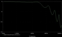
Regarding FEMM, even if you do get a simulation going, what would be your goal? Are you looking for electric field variation of no more than 50%, 10%, or 5%? I’m not trying to discourage FEMM work, only trying to suggest that you know what you’re seeking first. I have also worked on simulations of the acoustics of stators and gotten crude approximations of the frequency and transient response at the top of the audio band, but I’ve had to make very gross estimations of the acoustic properties of the stator. My point is that these tools give a designer some feedback about tradeoffs, but in the end, it’s the building, testing, and yes, listening, that matters. Just for fun, here’s an example near-field frequency response plot of a simulated ESL stator and diaphragm configuration (note the X-axis starts at 1 kHz and ends at 100 kHz). I’m awaiting a microphone good enough to verify these simulations!
The questions you are asking are very good ones. There are many opinions about these choices, but very little hard research, at least to my knowledge. A designer has many choices and tradeoffs among several design parameters: opening dimensions, stator conductor dimensions, d/s spacing, stator insulation materials and dimensions. By varying these parameters, many factors are affected: electric field strength, electric field uniformity, sensitivity, maximum SPL, acoustic reactance (reflections), acoustic resistance, acoustic noise (turbulence), etc. Right now, trading off these factors is an art more than a science. There are many rules of thumb about these tradeoffs, and most are based on trial and error. That’s OK, but be very wary when someone says that, for example, the hole-to-conductor area ratio MUST be X% - as if it’s a fundamental law of physics, because it is not. For example, Roger Sanders gives numerous guidelines for ESL design in his book, but these are soft on rationale and evidence – although I respect him for sticking his neck out and speaking from his experience. His guidelines are a good start, but only a start.
Regarding FEMM, even if you do get a simulation going, what would be your goal? Are you looking for electric field variation of no more than 50%, 10%, or 5%? I’m not trying to discourage FEMM work, only trying to suggest that you know what you’re seeking first. I have also worked on simulations of the acoustics of stators and gotten crude approximations of the frequency and transient response at the top of the audio band, but I’ve had to make very gross estimations of the acoustic properties of the stator. My point is that these tools give a designer some feedback about tradeoffs, but in the end, it’s the building, testing, and yes, listening, that matters. Just for fun, here’s an example near-field frequency response plot of a simulated ESL stator and diaphragm configuration (note the X-axis starts at 1 kHz and ends at 100 kHz). I’m awaiting a microphone good enough to verify these simulations!
Attachments
Hi,
Thanks for reply.
I have bought 0,5 mm^2 PVC insulated wire already.I decided to use it , because in my country i cannot get plastic grids(at least i have never seen them).Also , it was very cheap(approx 3-4$ for 100 meters).
I will try threaded steel rod for streching wires , as you suggested.
I am still trying to find suitable glue(epoxy does not bond to PVC at all).
Regards,
Lukas.
Better to encapsulate
Lukas: I would recommend that you find a low viscosity epoxy that bonds well to what ever you cross brace material will be using. Then you can string your stator wires and run a bead of the epoxy across each of the wires at each supporting cross brace. The epoxy will slowly run down around each wire finding its way to the cross brace where it will bond solidly. When set up (keep it level while it sets) the epoxy will have left enough of itself over top of each wire to encapsulate the wire firmly in place. Use a high quality epoxy. You may need to experiment with a few different viscosities to get it right. I would stay away from any adhesive that will actually melt PVC as you will no doubt end up compromising your dielectric strength should your insulation get thin as a result of an agressive solvent. Even if the PVC dielectric does not melt it will probably absorb a lot of solvent and expand which will also weaken its dielectric strength. An epoxy that essentially has no interest to react with PVC is what you want as long as it bonds well to the cross brace material.
What would be the size of your wire in American wire gage? Regards Moray James.
- Status
- Not open for further replies.
- Home
- Loudspeakers
- Planars & Exotics
- DIY Electrostatic - maximum safe db ?