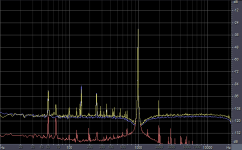
Improving on the test equipment described in a previous thread, I have constructed some circuitry dedicated to distortion measurements. It consists of one bandpass filter to purify a sine wave and then one notch filter to magnify the relative amplitude of distortion components.
Tests suggest that it can measure distortion down lower than -120dB. Much of the time that's lost below the noise floor. It's fixed at 1kHz only, but that's usually enough to get a good idea of how well a circuit performs.
You can read details on this page on my website.
Attached are some FFT results from the test equipment itself (red), an OPA134 (blue) and an OPA604 (yellow). Since the 1kHz fundamental is attenuated by 30dB by the notch filter, the magnitude of harmonics etc can be read directly off the scale. Note that the OPA604 is rubbish. You can also see a lot of noise picked up below 1kHz. I'm still working on trying to reduce that, although it doesn't affect this particular type of measurement.
Attachments
Nice. What's the filter made of, passive I presume? Hope you used air core inductors, I hear any kind of core will introduce distortion - for sure, no matter how little, it will show up at -120dB!
Tim
Tim
Both are active. I tried a passive RLC bandpass filter at first, but the distortion was significant. The required inductor size was too large for air-core, so I had to go active.
Still, the performance is very good, as you can see. I used an OPA227, which is a new one to me. It's quite possibly the best op-amp I've seen in terms of THD+noise.
Still, the performance is very good, as you can see. I used an OPA227, which is a new one to me. It's quite possibly the best op-amp I've seen in terms of THD+noise.
to get the 60Hz "spurs" down make sure that the test setup is completely shielded (I use a cookie tin), don't use a scope probe -- a piece of RG58 with a BNC on one end and a "directly soldered" connection to the DUT on the other, you can thread the RG58 through an E-Core which will also knock down some of the RFI. You don't want things like a soldering laying about either. These are all suggestions from Linear's Low Noise Measurement application guides and they work.
I use an SSM2019 as a 1000X noise amplifier -- the OPA227 (and its quad family member) would appear to make a dandy replacement in a differential configuration.
I use an SSM2019 as a 1000X noise amplifier -- the OPA227 (and its quad family member) would appear to make a dandy replacement in a differential configuration.
Thatnks for the advice. I am assaulted by EMI on all sides here.jackinnj said:to get the 60Hz "spurs" down...

I use Cool Edit. It's a very useful program for all sorts of audio things.ghg said:...Please, tell us about the FFT sw, you use...
The spurs are 50 and 100 Hz, the AC frequency being 50 Hz in Europe. However, I wonder what the 65 Hz spur might be (it's almost as strong as the 50 Hz).
capslock said:..I wonder what the 65 Hz spur might be ...
CRT monitor vertical frequency?

There are no CRTs in the room, and that spike is still there even when none of the ones in the house are on. The only equipment in close proximity is my PC + two LCD monitors (both of which refresh at 60Hz, not 65).moamps said:CRT monitor vertical frequency?
As an experiment .....
Mr. Evil
Can the refresh rate be altered? Gremlins in the mix seldom make any sense. Sometimes the only way to find them is to start a process of elimination.
Mark
Mr. Evil
Can the refresh rate be altered? Gremlins in the mix seldom make any sense. Sometimes the only way to find them is to start a process of elimination.
Mark
o get the 60Hz "spurs" down make sure that the test setup is completely shielded (I use a cookie tin),
I recently saw a powerpoint presentation by B. Whitlock of Jensen Transformers. In it he mentions that aluminum enclosures offer little shielding for low frequency -- for that you need a steel enclosure. Can anyone confirm or refute this? It it's a valid observation, you woild need a steel enclosure for AC power shielding.
Not only for the topic of this thread, but on other ocassions, this would be useful to know.
AudioWizard said:Found that here: http://www.zetatalk.com/info/tinfo22g.htm
Steel has a magnetic hysterysis that can effect your measurements. I pointed this out to Ben Duncan when he did his op-amp distortion article. You can get down to -140 dB with this technique. At 10kHz the air core inductor is less of a problem. I used a stock Sound Tech 1700 oscillator, LC filter, and PP/metal-film twin-tee (all passive). Rather than shielding I suspended everything in air away from most interference.
BTW that zetatalk site is run by one of the most notorious internet kooks of all time.
Audiowizard!
Thanks. That was an excellent link, especially since it described a test methodology that is easily repeated at little or no expense, rather than just and opinion. It's a keeper.
When dot-coms and some ISPs were failing and having babkruptsy sales a coulpe of years ago, you could pick up routers, switches and such for as little a $5. I got a few and tore out the inside just to get a cheap enclosure. They were usually steel rather than aluminum. Now I feel I got an even better deal than I thought at the time.
Hi Sam9,
I think that Jensen were correct but for different reasons alluded to by the following contributors.
The low frequency interference could be magnetic which can only be blocked by magnetic materials.
The high frequency interference would probably be electrical which can be blocked by any conductive materials.
Some large commercial manufacturers swear by non magnetic cases for their higher end wares allegedly due to the magnetic distortion their researchers find when testing their equipment. That is why a lot of manufacturers (large & small) have jumped on the bandwagon selling only aluminium cases, and some wood or no case at all.
I have not compared al to fe so cannot comment.
Mr Evil said:Improving on the test equipment described in a previous thread, I have constructed some circuitry dedicated to distortion measurements. It consists of one bandpass filter to purify a sine wave and then one notch filter to magnify the relative amplitude of distortion components.
Tests suggest that it can measure distortion down lower than -120dB. Much of the time that's lost below the noise floor. It's fixed at 1kHz only, but that's usually enough to get a good idea of how well a circuit performs.
You can read details on this page on my website.
Attached are some FFT results from the test equipment itself (red), an OPA134 (blue) and an OPA604 (yellow). Since the 1kHz fundamental is attenuated by 30dB by the notch filter, the magnitude of harmonics etc can be read directly off the scale. Note that the OPA604 is rubbish. You can also see a lot of noise picked up below 1kHz. I'm still working on trying to reduce that, although it doesn't affect this particular type of measurement.
Your results look nice.
I built wien-bridge oscillator from op37 with classical bulb stabilation. Best i could do was something 0.0007% distortion with OLD aureal wortex2. Needed quite heavy aweraging as this was at least 10db below noise floor. i couldnt find bulb that is specified in linear appnote anywhere but after trying couple of choices and fiddling around with component values i could reach that 0.0007%
I abandoned that project because at this low level of distortion oscillator took half an hour to stabilize and if i knocked pcb even lightly it went unstable. And sometimes it didnt start to oscillate, little knock on tin case and it started. Next life I am going to try LDR in feedback.
OPA604 is bad
My own measurements suggest that even OPA134 and OPA2134 have quite high THD, especially at supply voltages below +/-8V. The 0.0008% claimed in the datasheet will only stand at the most optimal conditions. At normal line level the real value is more like 0.01% from 20 - 20.000 Hz.
I recommend OPA627 which has ultra low THD under almost any circumstances, making it the best choice for building THD measurement filters.
Re: As an experiment .....
You are correct on that point -- I have traced problems to bad fluorescent bulbs, a soldering station which wasn't turned off, a nearby power cord which should have been out of the way, inadvertent mxing of two signals.
Recent edition of EDN described how some troubleshooting was done using the discarded magnetic head of a floppy disk-drive as a sniffer.
There is a parallel thread going with regard to diode snubbers (and this is in seemingly simple linear supplies) -- the RFI generated by a power supply can be many microvolts and the frequency can vary from a few tens of kilohertz to several megahertz. this RFI will migrate back the power supply cord, skipping over the transformer due to its capacitative coupling...the line cord acts like a radiator (antenna).
mwmkravchenko said:Mr. Evil
Can the refresh rate be altered? Gremlins in the mix seldom make any sense. Sometimes the only way to find them is to start a process of elimination.
Mark
You are correct on that point -- I have traced problems to bad fluorescent bulbs, a soldering station which wasn't turned off, a nearby power cord which should have been out of the way, inadvertent mxing of two signals.
Recent edition of EDN described how some troubleshooting was done using the discarded magnetic head of a floppy disk-drive as a sniffer.
There is a parallel thread going with regard to diode snubbers (and this is in seemingly simple linear supplies) -- the RFI generated by a power supply can be many microvolts and the frequency can vary from a few tens of kilohertz to several megahertz. this RFI will migrate back the power supply cord, skipping over the transformer due to its capacitative coupling...the line cord acts like a radiator (antenna).
scott wurcer said:
BTW that zetatalk site is run by one of the most notorious internet kooks of all time.
Well, I just pointed out a link where someone seemed to have done some measurements of this "steel vs. aluminium" thing, but after that, I took a look at the web site itself and realized it was kind of... weird.
I'm not backing up this article in any way; just thought it could give some ideas.
As for me, I'm absolutely not convinced there is any real difference in terms of shielding between aluminium and steel, and especially in the low-frequency area. A good, grounded aluminium shielding should be more than adequate - if it's not, there may be some other problem with the design/layout. Almost all "EMI shielding boxes" used in electronics are made of aluminium. I may be wrong, but that's not something I would worry about...
Another thing: in this article, the guy seems to think the thicker the shielding, the better: I don't think that Faraday would necessary agree. I myself would tend to think that thicker is better against very high frequency EM radiation, but not for low-frequency.
Anyway, interesting topic nevertheless.
Re: OPA604 is bad
As well it should be: the OPA627 costs almost ten times as much as the OPA134. (Around $20 a piece.) If you only need one or two, it's ok. But more than that, and you'll need to win the lottery. ;-)
Lars Clausen said:
I recommend OPA627 which has ultra low THD under almost any circumstances, making it the best choice for building THD measurement filters.
As well it should be: the OPA627 costs almost ten times as much as the OPA134. (Around $20 a piece.) If you only need one or two, it's ok. But more than that, and you'll need to win the lottery. ;-)
- Status
- Not open for further replies.
- Home
- Design & Build
- Equipment & Tools
- DIY distortion measurements better than -120dB