had nothing to do at school, so printed out the 2 PDF files. good read, i dont get everything yet, but i can try some stuff out.
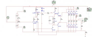
added the CCS to, distortion didnt really chance.
i didnt like the fact that the amplification became less at low frequenties, and my teacher told me to remove C2, and that solved it indeed.
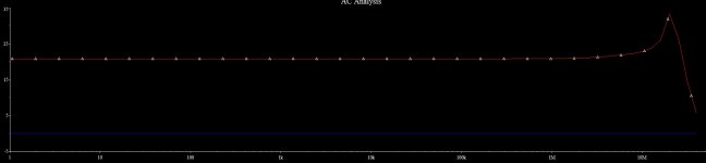
only it had a bump around 20Mhz, but that isnt used for audio, so i dont think its that bad.
for the cemaric cap, the only capasitor it has is C1, and thats a low value one, i was thinking of silver mica for it, but is ceramic better?
any more comments/ideas?
added the CCS to, distortion didnt really chance.
i didnt like the fact that the amplification became less at low frequenties, and my teacher told me to remove C2, and that solved it indeed.
only it had a bump around 20Mhz, but that isnt used for audio, so i dont think its that bad.
for the cemaric cap, the only capasitor it has is C1, and thats a low value one, i was thinking of silver mica for it, but is ceramic better?
any more comments/ideas?
Attachments
Silver mica is often preferred. The thing to understand with C1 is that the lower this value is, the lower the distortion. The higher it is, the more stable the circuit is. Realistically, you want to use a cap only large enough to keep the amp reasonably stable. AFAIK, silver mica has very good characteristics and so using this can improve performance. I really don't know the details. Personally I would use whatever's cheaper for experimenting. As long as it doesn't vary widely with voltage and cause distortion, it should be well enough.
As far as frequency response, the ear can't hear below 20Hz. I would aim for a frequency response of at least -3db at 20Hz. There is a reason for the input capacitor; it protects the amplifier, and protects your source if you amp goes wrong. It would also be good to add some HF/RF filtering at the input to keep the amplifier from having to deal with radio signals and ultrasound trash while dealing already with the audio signal itself.
- keantoken
I don't know if its helpful here, but I had a similar spike in one of my CDoms.
Bigger I made it , peakier it got. There seemed to be no Phase Margin win
but increase CDom till the slew of the amplifier could not keep up at 20KHz.
Mutilating the signal into an "unconditionally stable" triangle wave...
I later added some resistance in series with CDom to reduce the Q.
That got me stable with a reasonable cap, and without the weird peak.
I wonder if theres any benefit to cripple every transistor with small stagger
tuned caps? At least then you won't have any two FT poles shifting around
a similar pivot point. Or so I theorize without any experiment to back it up...
Last edited:
You see, I had just read Harman/JBL paper about a discrete op-amp.
It was posted in one of the other threads, I'll copy the link for you.
http://www.harman.com/EN-US/OurComp...ip/Documents/Scientific Publications/1091.pdf
In the top right paragraph of page 291 (page 2 of the PDF), you see
the JBL engineer harpin how great is the useful bandwidth of his output,
cause its got a different FT for each transistor. Maybe so... I don't know...
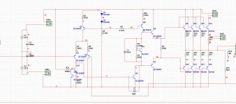
i found some time to work on this again.
my plan is to make a opamp, so the PCB would have the same pins as a normal opamp:
power supply, inverting and non inverting inputs and an output.
this because i might find other uses for a high current opamp, and not only audio.
so for audio, input filters and such are a worry for later on, lets get a nice opamp running first.
when looking at other opamp designes i saw that current sources are used a lot, do they improve the opamp, and if so, why?
i added a current source under Q3, the input transistor and distortion got a little bit lower.
if current sources indeed improve the opamp, what transistors would benefit from a current source instead of a resistor?
Attachments
Current sources make it more efficient, that's all. You'll want to use current sources in the power stage mostly.
If you look at the Vcb of Q17, you'll find that it's deep in saturation. It can't act like a true current source this way. However, you could improve performance the same way by using a current mirror. Look at this.
Not only would this perform the constant current function you mentioned, it would also double the gain of the LTP.
One reason for using current sources is efficiency, but it's not the main reason. Any electronic device will perform better working into a lighter load. A current source is used when you need to bias a component into its linear range of operation, but where using a resistor would unnecessarily add loading, causing the given component to work harder and distort more.
On a side note I recommend to put a diode in series with Q5's emitter to avoid sending the mirror into saturation.
- keantoken
An externally hosted image should be here but it was not working when we last tested it.
Not only would this perform the constant current function you mentioned, it would also double the gain of the LTP.
One reason for using current sources is efficiency, but it's not the main reason. Any electronic device will perform better working into a lighter load. A current source is used when you need to bias a component into its linear range of operation, but where using a resistor would unnecessarily add loading, causing the given component to work harder and distort more.
On a side note I recommend to put a diode in series with Q5's emitter to avoid sending the mirror into saturation.
- keantoken
As mentioned before C1 is for stability. Your sim may not show you any instability, but the amp when built may be unstable. The best way to check for stability and adjust C1 is by checking the open loop phase margin.( instability occurs when the output phase shift hits 180 degrees and you still have open loop gain greater than 1. Search Middlebrook probe for info on how to sim open loop gain/phase)
- Status
- Not open for further replies.
- Home
- Amplifiers
- Solid State
- diy discrete high power opamp