The post in the newcomer reporting area has been closed
This device is purely a personal DIY, and all the components come from online shopping. There is only one device, and I am not some kind of equipment supplier.
Basic idea:
TPA3255(600w) x 6 + 50V1000W + 15V+/- Switching Power + LT3045/LT3094 + 7*JRC5532DD + miniPC + Terratec 7.1USB sound card + Roon Server
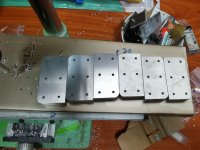
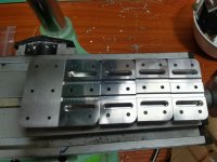
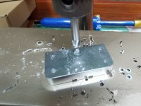
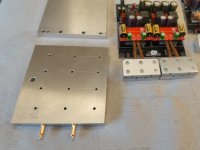
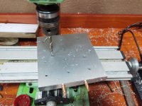
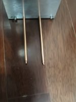
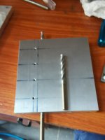
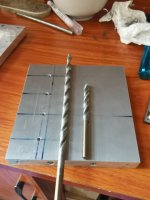
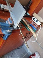
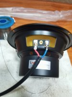
TPA3255 radiator renovation

Attachments
-
 IMG_20250301_201338.jpg287.8 KB · Views: 83
 -
 IMG_20250301_201521.jpg321.8 KB · Views: 82
 -
 IMG_20250301_202031.jpg260.8 KB · Views: 85
 -
 IMG_20250301_213824.jpg430.6 KB · Views: 86
 -
 IMG_20250531_170214.jpg392.3 KB · Views: 91
 -
 IMG_20250601_113116.jpg246.5 KB · Views: 87
 -
 IMG_20250601_115628.jpg295.9 KB · Views: 84
 -
 IMG_20250601_120435.jpg402.3 KB · Views: 89
 -
 IMG_20250601_165213.jpg194.3 KB · Views: 111
 -
 IMG_20250601_211743.jpg536.9 KB · Views: 101

Though analogue short-wave broadcasting is already built into a Class-D amp (only antenna required) you seem to want to broadcast digitally !!!

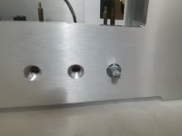
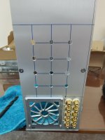
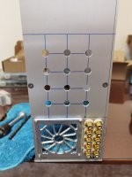
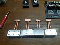
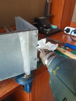
That's a simulated ground. The heat pipe radiator is connected to the aluminum alloy chassis
and there is a 0.25mm thick ceramic thermal conductive sheet insulation between TPA3255 and the copper radiator
and there is a 0.25mm thick ceramic thermal conductive sheet insulation between TPA3255 and the copper radiator
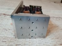
I see a lot of heat pipes going into a thick aluminum block, but what's the plan to get the heat out of that block again? Nice machining though!
Regarding the overall design, if each of the 6 channels provides 600W, it might be better to have each channel amp close to their speaker, and distribute low power signals.
Regarding the overall design, if each of the 6 channels provides 600W, it might be better to have each channel amp close to their speaker, and distribute low power signals.
Nice project. But Terratec 7.1 USB sound card is a entry level sound card. Only 16 bits. You need something better.
Last edited:
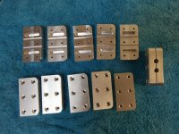
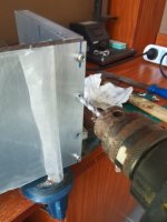
There are also drilled holes in the middle of the thick aluminum block (15mm) to embed copper heat pipes, which conduct heat to the thick aluminum plates (10mm) on both sidesI see a lot of heat pipes going into a thick aluminum block, but what's the plan to get the heat out of that block again? Nice machining though!
Regarding the overall design, if each of the 6 channels provides 600W, it might be better to have each channel amp close to their speaker, and distribute low power signals.
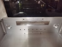
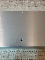
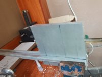
These thick aluminum plates are rigidly connected to the upper and lower aluminum plates of the shell for heat dissipation
At the same time, enclosing the power amplifier circuit board with thick aluminum plates is also to shield electromagnetic wave interference.
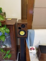
Six speakers are distributed around the room, which is far away.
If an unenhanced 0.5V audio signal is used for transmission, it is more likely to be interfered with
Attachments
-
 IMG_20250517_210646.jpg186.9 KB · Views: 49
 -
 IMG_20250517_210635.jpg165.8 KB · Views: 62
 -
 IMG_20250510_100129.jpg169.5 KB · Views: 46
 -
 IMG_20250510_100118.jpg235.1 KB · Views: 55
 -
 IMG_20250510_100025.jpg185.5 KB · Views: 53
 -
 IMG_20250510_094329.jpg389.3 KB · Views: 46
 -
 IMG_20250510_092714.jpg216.1 KB · Views: 56
 -
 IMG_20250510_092710.jpg220.6 KB · Views: 45
Last edited:
"Broadcasting" ... what do you really mean by this?
//
Roon Server 2.0 software is installed on miniPC, even if the amplifier circuit board is not powered on
He can provide lossless audio to any phone or PAD at home through a 1000M network
Or establish your own online live radio station
This is the meaning of "Broadcasting"
Nice project. But Terratec 7.1 USB sound card is a entry level sound card. Only 16 bits. You need something better.
5.1/7.1 channels, do you have a better recommendation?
This one is USB5.1/7.1 channels, do you have a better recommendation?
https://www.amazon.com/Asus-XONAR-U7-MKII-90YB00KB-M0UC00/dp/B06ZZNR4HQ/ref=sr_1_1
But if your Intel I9 mini PC can accommodate PCI sound cards then even those are available with CM9882 chipset.
https://www.amazon.in/CM9882A-Bracket-Compatible-Surround-Equipment/dp/B0CF1243YJ
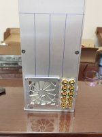
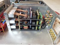
Capacitor array, 22000uF * 6, operating voltage 50V, with redundancy for safety period, withstand voltage 80V
Decoupling capacitor 1uF * 4+0.1uF * 4+0.01uF * 4+0.001uF * 4
Attachments
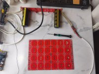


You probably should clamp these caps to the aluminium sheet or at least use silicon to the PCB. They are pretty long. Are you sure JCCON caps are reliable?
It would be better to use PCB connectors for the wiring as soldering such thick wiring to PCBs together with possible mechanical force is asking for peeled off PCB tracks.
Nice project, good heatsink solution!
It would be better to use PCB connectors for the wiring as soldering such thick wiring to PCBs together with possible mechanical force is asking for peeled off PCB tracks.
Nice project, good heatsink solution!
Last edited by a moderator:
This one is USB
https://www.amazon.com/Asus-XONAR-U7-MKII-90YB00KB-M0UC00/dp/B06ZZNR4HQ/ref=sr_1_1
But if your Intel I9 mini PC can accommodate PCI sound cards then even those are available with CM9882 chipset.
https://www.amazon.in/CM9882A-Bracket-Compatible-Surround-Equipment/dp/B0CF1243YJ
Thank you.
I checked the information and found that the Asus XONAR-U7-MKII uses the CM6632A chip, and it seems that the Terratec 7.1 USB it is currently using is also CM6632A. However, Asus' other components are obviously better
The PCIe sound card cannot be used, the mini PC is too small and does not have a desktop computer slot
Last edited:
Flat chassis surfaces are pretty limited (by the chassis area, obviously) in how much heat exchange to air they can provide. How much power do you think you will need to dissipate?
Assuming 90% efficiency, and running the system at full power (600 W peak) with 14 dB crest factor (supposedly a reasonable assumption for many types of music), which yields 100 W average power per channel, would give 10 W power loss per channel. Figure 10 from the TI datasheet indicates 20% loss might be a safer assumption. So that adds up to 120 W dissipation if you ran the amplifier all out. To keep the amp surface at a reasonable temperature (30K above ambient), you'd need a heatsink with 0.25 K/W thermal resistance, or about 7000 cm^2 of surface area. A 43cm wide chassis would have to be about 75cm deep, assuming both the top and bottom outside surface contribute. Since even when you run the system full out, only two or maybe three (subwoofer) channels contribute meaningfully, therefore maybe a 43 cm wide by 43 cm deep chassis, with solid top and bottom well connected to the heat pipes, might be sufficient, to my surprise.

Assuming 90% efficiency, and running the system at full power (600 W peak) with 14 dB crest factor (supposedly a reasonable assumption for many types of music), which yields 100 W average power per channel, would give 10 W power loss per channel. Figure 10 from the TI datasheet indicates 20% loss might be a safer assumption. So that adds up to 120 W dissipation if you ran the amplifier all out. To keep the amp surface at a reasonable temperature (30K above ambient), you'd need a heatsink with 0.25 K/W thermal resistance, or about 7000 cm^2 of surface area. A 43cm wide chassis would have to be about 75cm deep, assuming both the top and bottom outside surface contribute. Since even when you run the system full out, only two or maybe three (subwoofer) channels contribute meaningfully, therefore maybe a 43 cm wide by 43 cm deep chassis, with solid top and bottom well connected to the heat pipes, might be sufficient, to my surprise.
Flat chassis surfaces are pretty limited (by the chassis area, obviously) in how much heat exchange to air they can provide. How much power do you think you will need to dissipate?
Assuming 90% efficiency, and running the system at full power (600 W peak) with 14 dB crest factor (supposedly a reasonable assumption for many types of music), which yields 100 W average power per channel, would give 10 W power loss per channel. Figure 10 from the TI datasheet indicates 20% loss might be a safer assumption. So that adds up to 120 W dissipation if you ran the amplifier all out. To keep the amp surface at a reasonable temperature (30K above ambient), you'd need a heatsink with 0.25 K/W thermal resistance, or about 7000 cm^2 of surface area. A 43cm wide chassis would have to be about 75cm deep, assuming both the top and bottom outside surface contribute. Since even when you run the system full out, only two or maybe three (subwoofer) channels contribute meaningfully, therefore maybe a 43 cm wide by 43 cm deep chassis, with solid top and bottom well connected to the heat pipes, might be sufficient, to my surprise.
View attachment 1472003
Thank you for your rigorous mathematical calculations. Actually, I can't quite understand them either, I just DIY based on my intuition
In addition to passive heat dissipation, there are two heat dissipation fans on the back of the casing. I have connected a temperature switch of 40 degrees Celsius in series, which will operate when the temperature exceeds 40 degrees Celsius. One will blow inward and the other will blow outward
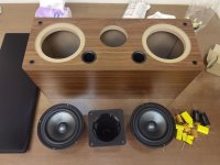
I feel that the heat dissipation of TPA3255 is not as impressive as I thought. My speakers are two front speakers, dual 10 inch+6 inch+4 inch, two surround speakers, 5 inch+3 inch, dual 6 inch+4 inch horns in the middle, and a 12 inch subwoofer
In actual operation, the ambient temperature at home is 30 degrees Celsius, the volume is acceptable to the ears at 25%, and the two fans have never been turned on
Attachments


Last edited:
Last night, I opened the sound card casing and confirmed that the chip used in the Terratec 7.1 USB sound card is CM6206, which is indeed a 16 bit DACThis one is USB
https://www.amazon.com/Asus-XONAR-U7-MKII-90YB00KB-M0UC00/dp/B06ZZNR4HQ/ref=sr_1_1
But if your Intel I9 mini PC can accommodate PCI sound cards then even those are available with CM9882 chipset.
https://www.amazon.in/CM9882A-Bracket-Compatible-Surround-Equipment/dp/B0CF1243YJ
- Home
- Amplifiers
- Class D
- DIY D-class amplifier+digital broadcasting all-in-one machine