I was interested in learning about this to control mic preamps like the that 1570. What is the smallest amount of board space you think you could condense this down to without it being a remote control, ie a tiny screen and two buttons ?
you can bury a controller chip under the OLED display. I put a large 328 atmega chip there, thruhole, but on a real board I'd use a smd controller and those can be small as 8 pins if you have a very simple job to do.
if you plan any bitmaps at all (icons) you need to think about that for controller size. I picked the classic arduino since it does have lots of program flash space and you can use that for also storing byte arrays of graphic icon bitmaps. if you have a graphic display, it kind of makes sense to make use of -some- kind of graphics. otoh, there are line and box and shape drawing primitives in the u8glib library, for example, so you can draw your graphics if you want, maybe taking up less flash space.
the simplest of these oled displays is 2 wire i2c-like. its not proper clean i2c so there are workaround private drivers for that and that u8glib handles all the comms stuff as well as graphics and text stuff. I do recommend it. the display takes 3v or 5v and so you can get by with 4 wires to it, if you have to squeeze that display in somewhere. like, even, on existing gear! but also note, there is no good mounting for those displays. the holes on the top are ok but bottom ones often are too close to the glass. and it is real glass on top, so be careful. its cheap and thin and can break if you are rough with it. it comes in 2 colors: white and blue. white seems harder to find and blue is very common. there are 2 sizes, .96" and 1.3" and they are 99.9% compatible (128 pix across vs 132, mostly). pick the size you want. I went with the small one for this build but would use the 1.3" version in a real build. (I picked the smaller one on principle: if I can develop a small gui with text and some gfx, and with my old eyes still be able to see it on the small screen, then the big screen will only be better, but not -essential-). so, I am using the small one but I would pick the 1.3" for real use. I might take a pic of them both side by side so you can see how much bigger the 1.3 is. and they are usually nearly the same price, too!
buttons, you pick what you want, so I can't comment on how that will dominate the box size. I like the tactile industrial buttons of various kinds. I browsed mouser, picked a bunch of sample types and sizes and shapes and tried them out to see what felt good and usable to me. I bought a bunch of those angle buttons since the arrow keypad is such a common theme and that group of 4 or 5 will be on a few of my projects. the angled keys help you find 'home'. its good to find home! lol. part of the value-add of a diy remote like this is to engineer the feel so that it fits and works right for you. I'm still working on a better shaped/molded case for it, but I would probably keep the same keys that this proto has. unless you are going to make your own, this is as good as its going to get, button wise, on single unit quantity builds. that style of button body has been around for decades and I remember using them in a morse code memory keyer back in the 70's and 80's. so, its a proven design, those buttons, and you can get the square kind with all kinds of icons or actual arrows or words printed on them. they are not panel mount, but I consider that a good thing, in this case 😉
HTH
got a new Qi charging cradle from amazon, yesterday:

this is a triple-coil charging base, so it should have less sensitivity to sweet-spots for coil to coil alignment.
this is a triple-coil charging base, so it should have less sensitivity to sweet-spots for coil to coil alignment.

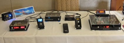
new functionality: both (actually, even 3 or more) units stay in sync.
volume can be changed from either side; the unit or the remote. if you go to one, the other needs to stay updated, and now it does. both units can GET as well as SET values.
its responsive, too. I'll try to shoot a demo video to show it in motion. turning the rotary encoder has the led display updating at its natural rate (which is instantaneous, essentially) and the remote oled display, while many times slower, does not seem to interfere. I've structured the code so that the display update is unhooked from the incoming serial command and reply stream. incoming data is always processed and so the unit (remote) always knows the current value, but the display might skip some middle values so that it keeps up. while the values are being changed, you do see the bargraph move and it keeps up nicely with the rotary, so the overall feel is acceptable.
there is a 3rd player, not shown, that also works. the IR to xbee gateway is another talker/listener and if you use a sony dvd (example) remote and program the gateway to send out xbee messages on the up/down sony ir messages, the preamp vol control engine does update, its display updates and the oled remote updates 😉 its a pretty cool demo, having 3 controllers and as long as you only send commands from one of them at a time, things are fine and everyone stays in sync.
a webserver (serial to xbee) adapter is next on my to-do list and it should play along just like the others, plus giving the phone and tablet guys their chance to play 😉
Once again, extremely impressive work.
Certainly puts my own feeble Arduino-attempts in perspective 😉
/U.
Certainly puts my own feeble Arduino-attempts in perspective 😉
/U.
thanks 😉
it was a long and slowly evolving journey. I didn't have to rush or fit into a time-line so I was free to wander and try things and see where they led.
the next burning amp event, in san francisco (actually, redwood city), is coming up real soon. I should have enough of this whole system working to bring and demo, there. I may even give a short presentation on the system design, communication details and prototype implementations. that is, IF I can get enough of everything all working together. this project touches code that will reside in quite a few boxes and systems and there is still so much more left to be done before the concept can really be demo'd properly. but, there is progress and so I'm encouraged 😉
more progress toward the large solution.
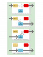
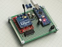
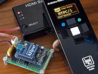
first, a document showing how IR and RF can both be used, as inputs and outputs, to control a miriad of devices. then, a proto board that implements that idea.
the first thing I used it for was to capture 2 IR codes; one from one remote and onefrom another - and store it inside this board. then, create a 'cross connect' so that when code-1 comes in over IR receiver, code-2 is sent out on the IR transmitter. I was able to have my sony dvd remote (that I like a lot) control my vizio tv. I only needed 1 button to be emulated (the on/off button, lol) and this does that job nicely. it saved me having to use a universal remote; in fact, this board acts like a universal remote of sorts.
the next thing I did with this was to convert other IR codes (on that same sony remote control) to xbee serial/ascii messages - that I listen for in my other DIY audio boxes. instead of having to use a custom remote, I can use any old ir handheld and still be able to (send only) commands to xbee-controlled systems.
I also plan to support xbee remotes (or, later on, webservers that have xbee on them) as sources and IR as destinations; so that 'dumb cd players' (or set top boxes) that only speak IR can be controlled with a fancy rf-based remote.
and lastly, if you need to translate ir to ir or xbee to xbee (to remap data or to talk to an older firmware box) that is also possible.
Attachments
more features 😉
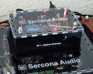
today, I added a new one that some may find interesting. I bought a DAP a few months ago (fiio x3-2) which is a really nice high-def audio player; has bit-perfect spdif/coax out at 192/24, has a nice cs4398 dac inside and even supports dsd (a dsd file is converted to pcm if sent out of the spdif-out port). it has line-out and phones-out, too.
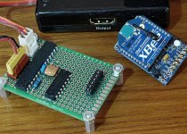
anyway, it has an inline-remote feature, like a play/pause/skip control on a phone headset. except this player does not use resistor programming for the button functions, it uses clicks on the 4th (trrs) band! well, ok, I can handle that 😉 the arduino now can watch for IR or xbee incoming commands (unused keys on my IR remote) and if a << or >> is pressed, the circuit sends out the right number of clicks on the 4th band to gnd. 1 click is play/pause, 2 clicks (120ms apart) is for skip-forward and 3 clicks is skip-backard a song. no seeking (that I found yet) but at least it has play/pause and skipping of songs.
I added a small 8pin ssr to the board and that's enough to 'click' the inline remote and have it do the right thing. LAA110 claire chip is a leftover from a previous project and it works just great, here.
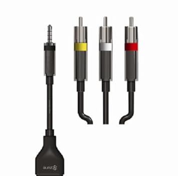
the zune cable (lol!) is the thing to get; it has the TRRS 1/8" connector and 3 rca's; the usual left and right audio but the 3rd is a video-out (for zune) and I'm using it as the clicker. short center to gnd on that yellow plug and the inline remote commands are acted on by the player.
cable is $10 or less (not bad quality, either). this is the one I got:
http://www.amazon.com/gp/product/B000IXLHOM
so, for those who might have a system that might benefit from remote control but uses the so-called inline remote protocol, this gateway circuit might be useful for you.
I will have it with me at the next bay area burning-amp event (october) and also this coming weekend at the head-fi event up near the san fran airport (burlingame, ca).
today, I added a new one that some may find interesting. I bought a DAP a few months ago (fiio x3-2) which is a really nice high-def audio player; has bit-perfect spdif/coax out at 192/24, has a nice cs4398 dac inside and even supports dsd (a dsd file is converted to pcm if sent out of the spdif-out port). it has line-out and phones-out, too.
anyway, it has an inline-remote feature, like a play/pause/skip control on a phone headset. except this player does not use resistor programming for the button functions, it uses clicks on the 4th (trrs) band! well, ok, I can handle that 😉 the arduino now can watch for IR or xbee incoming commands (unused keys on my IR remote) and if a << or >> is pressed, the circuit sends out the right number of clicks on the 4th band to gnd. 1 click is play/pause, 2 clicks (120ms apart) is for skip-forward and 3 clicks is skip-backard a song. no seeking (that I found yet) but at least it has play/pause and skipping of songs.
I added a small 8pin ssr to the board and that's enough to 'click' the inline remote and have it do the right thing. LAA110 claire chip is a leftover from a previous project and it works just great, here.
the zune cable (lol!) is the thing to get; it has the TRRS 1/8" connector and 3 rca's; the usual left and right audio but the 3rd is a video-out (for zune) and I'm using it as the clicker. short center to gnd on that yellow plug and the inline remote commands are acted on by the player.
cable is $10 or less (not bad quality, either). this is the one I got:
http://www.amazon.com/gp/product/B000IXLHOM
so, for those who might have a system that might benefit from remote control but uses the so-called inline remote protocol, this gateway circuit might be useful for you.
I will have it with me at the next bay area burning-amp event (october) and also this coming weekend at the head-fi event up near the san fran airport (burlingame, ca).
some feedback from the head-fi show, last weekend.
I met an audio magazine reviewer and we chatted for a bit. today, I see the arduino remote made his review!
Show Report: Head-Fi Meet, July 18, 2015 - HomeTheaterHiFi.com
I met an audio magazine reviewer and we chatted for a bit. today, I see the arduino remote made his review!
Show Report: Head-Fi Meet, July 18, 2015 - HomeTheaterHiFi.com
today, I put the little guy on a diet 😉
changed the battery to be a smaller one (still Qi charged, though). moved a bunch of things inside and learned from the first version.
1.25" on the old one (thickness) down to 0.6" on the new.
if I can come up with a good idea for the middle part (lol) this could be a usable chassis. maybe a layer of semi-stiff rubber that extends a bit beyond the plastic edges. would provide some protection against drops and bangs, plus a grip.
would love to have a wooden shell and then just add the plastic top and bottom to it.
anyway, the diet worked and the 'thick as a brick' look is dead 😉
Attachments
Jethro Tull passed away in 1741
Ian Anderson tells us that as of 2014 the group, Jethro Tull, is no more.
Ian Anderson tells us that as of 2014 the group, Jethro Tull, is no more.
The new slimmer remote looks better. A nice wood case with inset faces would be neat. That's a great idea.
Jethro Tull passed away in 1741
Ian Anderson tells us that as of 2014 the group, Jethro Tull, is no more.
"Everyday I see the mornin'
Come on in the same old way
I tell myself tomorrow brings me
Things I would not dream today."
JT had a nice long run. probably been 30 years since I last saw them, live.
Yup, definitely Ian A. was a thrill to see live. He is still touring around, IIRC maybe a couple of years ago he was doing small venues like our Casino Rama.
I do like your small graphic display. mfg#?
Ain't mech design a PITA 🙂 I do not think making carbon contact switches are all that difficult to do. The button label printing can be done somewhere 🙂 They do wear out, but I think all you do is re-apply the carbon gunk and clean the gold pads? Not done it myself!
With the graphics display, it sure cuts down on buttons and labels = I like
I have a xbee design in the works for a OBD2 reader. It is ready for fab but the customer needs to come up with a plan before I release it. I could easily use it as a template for your design and do up a small pcb. I need to learn to program xbee device as it is. I am sure I can use this device to control my radios if I put a xbee in them.
Last edited:
the small oled display is very popular with 'makers' right now. its a $10 part and can be found by search for 'oled 128x64 1.3"'. the i2c version is 4 wires but slow (not very fast for animation or motion, even page displays have visible redraw effect). the spi version is much faster and when the arduino uses its hardware spi, its 2x or even 4x faster and screen draws are nearly instant.
but remember, one down-side to this oled stuff is that it has limited run-time. that gives me pause, to some degree, since the rated lifetime is about 1-2 years of constant on-time. for a clock display, that would be bad. for a display that is 'on demand' and not always on, it could work. screen savers/blanking is also needed.
then again, for a DIY its fine. if you socket the display, then just buy spares and replace when the brightness starts to fade.
mounting that display is not easy, though. its not designed to be panel mounted and the mounting holes are not really useful (too close to the glass edges). what works for me is to solder the top pins to the board and to solder some wire to the 2 bottom holes that are solder-coated. that will secure the unit to a pcb below and THAT board can be chassis mounted or just be the main board, itself.
on a non-diy, I would probably make the display a board of its own with a connector and that way you can swap out the display without unsoldering, later on. stock the boards and displays as built-up modules and at least you have a solution that does not overly **** over the customers (remains to be seen, though).
I just really like the form factor of this display, how (mostly) simple it is to use, with the u8glib library and how there is no ghosting or contrast or side-view issues like old style lcd's. you have a few fonts sizes you can pick from and you can do limited 1-bit bitmaps for gfx, as well as discrete shape/line drawing.
Ya your way ahead of me, so more catch up/learning in the old mind, but all good ideas for a DIY project and hopefully a product = good luck 🙂.
I will have to get the Oled spec and look at it to see your mech issues. i see the advert now, of course, use spi over i2c for graphics. have you looked at FTDI FT800? Not for this remote of course🙂
I will have to get the Oled spec and look at it to see your mech issues. i see the advert now, of course, use spi over i2c for graphics. have you looked at FTDI FT800? Not for this remote of course🙂
Last edited:
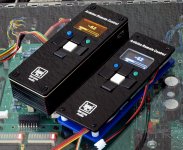
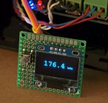
here's the method I'm using.
you can see how I soldered to the bottom eyelets. that seems to hold it in place well and its still un-doable if you need to remove it.
a friend had made some 3d printed plastic nibs that would fit into pcb holes below and are wide enough to hold the bottom eyelets. you then just melt the plastic like a rivet to lock the display in place. may not last and is not fix-friendly but its another idea on how to mount this.
also, be aware that these are supposed to run at 3.3v but some do run at 5. when at 5v, you may even see screen flicker. if so, run at less than 5 (4 is fine).
for the u8glib, you may have to do a trial and error to find the one C constructor that works for the module you bought. there are tons of clones and they vary. that's annoying, to be sure. if you plan to build many things with this module, you may want to buy them in bulk to make sure all your parts are the same. buying a new lot from someone, even the same seller, may not get you the same exact part again! a friend does buy directly from heltec and that can save your sanity.
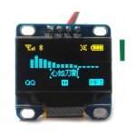
finally, they do make a dual color one but its lame. one group of lines of pixels at the top is yellow and the rest below is blue. I guess its good for a battery or antenna display like this, but seems too specific to be useful.
you can see how I soldered to the bottom eyelets. that seems to hold it in place well and its still un-doable if you need to remove it.
a friend had made some 3d printed plastic nibs that would fit into pcb holes below and are wide enough to hold the bottom eyelets. you then just melt the plastic like a rivet to lock the display in place. may not last and is not fix-friendly but its another idea on how to mount this.
also, be aware that these are supposed to run at 3.3v but some do run at 5. when at 5v, you may even see screen flicker. if so, run at less than 5 (4 is fine).
for the u8glib, you may have to do a trial and error to find the one C constructor that works for the module you bought. there are tons of clones and they vary. that's annoying, to be sure. if you plan to build many things with this module, you may want to buy them in bulk to make sure all your parts are the same. buying a new lot from someone, even the same seller, may not get you the same exact part again! a friend does buy directly from heltec and that can save your sanity.
finally, they do make a dual color one but its lame. one group of lines of pixels at the top is yellow and the rest below is blue. I guess its good for a battery or antenna display like this, but seems too specific to be useful.
Attachments
- Status
- Not open for further replies.
- Home
- Source & Line
- Analog Line Level
- diy custom remote for my preamp