I did not use the dc coupling capacitor. I will probably post the results of the class A2 test as a new topic.
Alfredo
Alfredo
It will be interesting to see how much current that thing can source and how much distortion results.
I have been considering a curve tracer but would make it microcontroller based(I want to record curves to import to excel) so I am interested in how this high-voltage chipamp performs.
The first tube curve tracer I built was based upon a Basic Stamp -- and I reconfigured a Heath HV supply with a 10-bit DAC to drive the grid voltages etc., etc. The Stamp is quite easy to program, but data exchange to Excel via the serial port was pretty slow. A few years ago easily configurable USB interface became available.
A diff amp can be easily configured as a precision current source -- see the Linear Tech data sheet for the LT1990. With a resistor, the current source becomes a voltage source, although a buffer might be required....

With help (and a lot of patience) from Steven Parfitt (TheGimp) the belated project of my curve tracer is coming along. Still a breadboard setup but works.
Clock is derived from rectified mains (clock of 100Hz in UK) and 8 curves are plotted. Refresh is acceptable, but not perfect. However, the circuit is much simpler this way.
Attached is a sample test of a 45 valve 😀
Will post more details later...
Cheers,
Ale
Clock is derived from rectified mains (clock of 100Hz in UK) and 8 curves are plotted. Refresh is acceptable, but not perfect. However, the circuit is much simpler this way.
Attached is a sample test of a 45 valve 😀
Will post more details later...
Cheers,
Ale
Attachments
Looking good Mogliaa
I hooked the LM49810 to he step generator today. I am only using the bench supply with +-40V. The picture below is 60Vpp. Now I need to work on injecting bias to it and having control of the volts per step. In the picture, there is 30V above ground and 30V below ground. The volt per steps are at 5V. For the bias, I am thinking about floating LME49810 power supply and injecting a variable negative voltage to the transformer center tap. Is there an easier way of doing it without affecting the grid of the tube under test?
For the volts per steps i need to pre amplify the step to get double what I am getting now, this will give me up to 10V per step. I have a spare op amp in the cuircuit. This will also invert the steps.
I am still using the same control of steps per family as before so I can go to a very large number of steps per family. The problem is the refresh rate. But.. I gave myself a Christmas present, a 100mhz DSO. Shouldn't have problems capturing the data to a the PC.
More later...
An externally hosted image should be here but it was not working when we last tested it.
Originally my plan was to produce a negative and positive grid driver to enable testing of power tubes with positive grid current. TheGimp helped me out in designing the driver with op amps, MOSFET stages and feedback loop. I gave up when trying to stabilise the circuit so ended up with a simplified version with op amp to set bias and a couple of P MOSFETS.
The staircase is a CD4520 counter from the mains clock as per Merlin's design.
Anode sweep is also mains rectified and a MOSFET in source follower driving the valve. Have a pair of 230/24V back to back transformers which after rectification give about 350V max sweep.
At the moment the blurred lines or double lines on the curves are due to the breadboard noise and long cables. My current sensing resistor is 10 ohms which then provides the Y signal for amplification via a differential amplifier and inverter as per Goote's design above.
Need to etch the PCB and see if gets ok in the end, with a sharper set of curves once everything is tightly wired and shielded.....
Cheers,
Ale
mogliaa, how to you wire the op amp to setup the bias? High much bias is possible like this?
I added a few pots to the board. Ended up having to use a preamp and a pot to control the gain of the LME4910. I am able to get volts/step from .5V up to 10V.
I am hooking up a tube next.
I added a few pots to the board. Ended up having to use a preamp and a pot to control the gain of the LME4910. I am able to get volts/step from .5V up to 10V.
I am hooking up a tube next.
An externally hosted image should be here but it was not working when we last tested it.
An externally hosted image should be here but it was not working when we last tested it.
An externally hosted image should be here but it was not working when we last tested it.
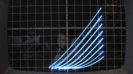
Did a test with a 1619 trioded. I dont have a bias circuit yet so basically the lme49810 is putting out a symmetrical step centered around 0V. In the picture below the volts per step are not calibrated,they are around 10 volts. The third curve is very close to the zero volt step.
The tube is going to around +15v on the grid, pulling 10ma from the lme49810.
I tried biasing the grid steps by using a blocking cap and a resistor, it works but it wont source current on the positive grid steps. When i connect the grid directly to the output of the chip it does feed current to the grid. I will try to float the chip and inject the bias on its ground pin. Hope it works.
An externally hosted image should be here but it was not working when we last tested it.
Still no adjustments to the volt/step. Steps are around 4.5v/step. First one at 0v. I think that the IC works fine, it has a large voltage swing for power tubes and can source some current for the positive grid region.
Now I need to fine tune things (bias method as well) and build it. By the way, the step generator on this one is a little different. Based on your recommendations I tried the 4 bit ripple counter. I still used a 240hz clock that I derived from the mains frequency (using PLL and divider). I can still use a comparator to reset the counter and control the steps per family. I used a AD7528 8 bit dac I had laying around, works just fine. I will play a little more with it as it has two outputs that can be enabled separately. Be changing the connection of the 4 bits to the DA I can change the output voltage of the ladder. So I can basically have an enable toggle that doubles that selects from either DAC output. One output could be 1/2 of the other.
Now I need to fine tune things (bias method as well) and build it. By the way, the step generator on this one is a little different. Based on your recommendations I tried the 4 bit ripple counter. I still used a 240hz clock that I derived from the mains frequency (using PLL and divider). I can still use a comparator to reset the counter and control the steps per family. I used a AD7528 8 bit dac I had laying around, works just fine. I will play a little more with it as it has two outputs that can be enabled separately. Be changing the connection of the 4 bits to the DA I can change the output voltage of the ladder. So I can basically have an enable toggle that doubles that selects from either DAC output. One output could be 1/2 of the other.
An externally hosted image should be here but it was not working when we last tested it.
I used a variant of this supply from "The Art of Electronics" for my tube tracer article in AX about 9 years ago -- but I explicitly set the bias for the first MOSFET -- if you work with the loop compensation you can get a very linear HV supply which will swing 400 or 500 volts. I used a 10 bit DAC for the ramp generator:
Attachments
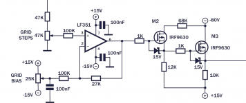
Attached is what I'm using as the grid driver. I feed the output of the CD4520 counter resistor ladder on to the op amp. With this circuit you can easily generate all ramps required starting from 1V steps. Is handy enough and reduce complexity of the overall circuit.....
Still experimenting 🙂
Still experimenting 🙂
Attachments
Still no adjustments to the volt/step. Steps are around 4.5v/step. First one at 0v. I think that the IC works fine, it has a large voltage swing for power tubes and can source some current for the positive grid region.
Now I need to fine tune things (bias method as well) and build it. By the way, the step generator on this one is a little different. Based on your recommendations I tried the 4 bit ripple counter. I still used a 240hz clock that I derived from the mains frequency (using PLL and divider). I can still use a comparator to reset the counter and control the steps per family. I used a AD7528 8 bit dac I had laying around, works just fine. I will play a little more with it as it has two outputs that can be enabled separately. Be changing the connection of the 4 bits to the DA I can change the output voltage of the ladder. So I can basically have an enable toggle that doubles that selects from either DAC output. One output could be 1/2 of the other.

Nice ones!, is looking really good😀
I used a variant of this supply from "The Art of Electronics" for my tube tracer article in AX about 9 years ago
Hi Jackinnj
Is your article available somewhere for download?
On your drawing, are you talking about biasing Mosfet itself or about shifting the ramp up or down within a range (with no amplification).
Alfredo
Attached is what I'm using as the grid driver. I feed the output of the CD4520 counter resistor ladder on to the op amp. With this circuit you can easily generate all ramps required starting from 1V steps. Is handy enough and reduce complexity of the overall circuit.....
Still experimenting 🙂
I think i need something similar to this, but need to play with the LME49810 rails.
I think the ground connection needs to be virtual otherwise I would loose the benefit of the full voltage swing.
An externally hosted image should be here but it was not working when we last tested it.
Hi Jackinnj
Is your article available somewhere for download?
On your drawing, are you talking about biasing Mosfet itself or about shifting the ramp up or down within a range (with no amplification).
Alfredo
1) I don't think that they have PDF's of the article -- it's ancient history at this point and I know a lot of things I would do differently.
2) The steps were generated by a 10 bit Maxim DAC and I just used a bit-banging RS-232 program to generate the steps -- quite slow back then. There several ways to bias the first MOSFET -- but you can just get a DAC with an outboard reference provision.
It's nice to see the output on a computer screen, or CRT -- what made the program more useful was that the data was downloadable to Excel. Today there are a number of programs to take the data and create the SPICE parameters.
On a Tek curve tracer, the cathode of the DUT (Device Under Test) is always grounded. The current sense resistor is in the ground leg of the plate supply. Current waveforms are inverted, but that is easy to fix. Also, the grid drive is referenced to ground and that is handy.
For testing pentodes the screen supply also returns to ground via a separate current sense resistor. (not 100% sure on this)
I don't recall if the 570 does it, but on the 576 you can select 2x the grid step rate so the grid drive changes at the peak of the plate supply waveform. This reduces the flashing on the display. The 576 is limited to 10 steps of grid drive. On the 570, the right/left switch used for matching DUTs connects the step generator to one device, both devices get a large negative voltage to bias them off when they are not selected. On the 576, the switch disconnects both base and collector (grid and plate) supplys from the DUT.
On the 576 there is a selectable voltage limit imposed on the base current drive so that it doesn't go to the rail if the specified current does not flow. This is especially important since you can dial in an offset to base current or voltage drive.
The first thing you do when testing a tube on the 570 is adjust the heater voltage. That's what the large meter on the front is for. You can also watch what the effect of changing heater voltage has on the curves. Think those power tubes are matched? Make sure they get exactly the same heater voltage!
I am actually following a few of the 570 concepts. I am sensing current as described above. Also use the 2x by using the 240hz rate, hence the PLL. I am also using the same phase matching between the grid and plate supply, using a .05uf cap and a 250k pot, works really well to clean up the xy display. Also i am planing to use the same plate series resistors as the 570. The series resistor is what makes the curves end in the diagonal seen on my pictures.
Non DIY Tracer:
An externally hosted image should be here but it was not working when we last tested it.
Nice!
I was able to play with the negative bias configuration. Very similar to post 31. I had to float the PS of the LME49810 and inject the negative bias to the common of the floating supply. I had to remove the feedback cap on the chip so that it also amplifies dc. This way with a small dc shift of the input signal I can move the output easily. I did this test with my signal generators dc offset function. For the real circuit I would need to change my buffer staircase op amp at the output of the DAC from a single supply to a dual supply one so I can give it some negative offset.
I was able to play with the negative bias configuration. Very similar to post 31. I had to float the PS of the LME49810 and inject the negative bias to the common of the floating supply. I had to remove the feedback cap on the chip so that it also amplifies dc. This way with a small dc shift of the input signal I can move the output easily. I did this test with my signal generators dc offset function. For the real circuit I would need to change my buffer staircase op amp at the output of the DAC from a single supply to a dual supply one so I can give it some negative offset.
Hi can you post your PLL circuit? I'm keen to see whether I can add a simple stage to increase clock above 100Hz and improve refresh cycle.
Thanks
Ale
Thanks
Ale
- Status
- Not open for further replies.
- Home
- Design & Build
- Equipment & Tools
- DIY Curve Tracer