I'll try to help.
I have a couple of questions.
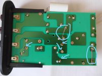
I have circled two areas on the copper side of the board where you've placed wire.
What are those for? Are they jumpers between traces?
I prefer to mount everything on the other side of the board, but I've only worked on a few pcb's and even fewer crossovers. Helps me to keep everything lined up.
Also, the picture wasn't very clear but I marked arrows where the soldering looks like it might be a little suspect. Maybe take the time to reflow those joints at least. It should look like a hershey's kiss (climbing up the leads) when you're done.
I have a couple of questions.
I have circled two areas on the copper side of the board where you've placed wire.
What are those for? Are they jumpers between traces?
I prefer to mount everything on the other side of the board, but I've only worked on a few pcb's and even fewer crossovers. Helps me to keep everything lined up.
Also, the picture wasn't very clear but I marked arrows where the soldering looks like it might be a little suspect. Maybe take the time to reflow those joints at least. It should look like a hershey's kiss (climbing up the leads) when you're done.
Attachments
Last edited:
The woofer and tweeter share the input terminals from the amp. If you measure between w- and t- you'll see a short. If you measure between the two input terminals you should see about 7 ohms via the woofer circuit.simo8n said:continuity between HF and LF, on both speakers. So there is definitely something wrong
Therefore you'll measure something between the drivers at any driver terminal.
GordB, if you look at post 5 where I posted the picture of the pcb with instructions, there are 3 links to be made. Those 2, and the third I made on the other side of the pcb.
I have finally been able to fit the crossovers. However, I do have continuity between HF and LF, on both speakers. So there is definitely something wrong somewhere?
But do they work? Do you have sound now?
Remember that as a general rule all the drivers in a simple crossover share the same common connection, in other words what we might call the 'negative', this being one of the connections back to the amplifier.
So one terminal of each driver should connect directly to the input sockets
The bass drivers other terminal should have continuity back to the other input terminal through at least one series coil. There will be other parts as well but that basic continuity should be present.
The tweeters other terminal normally has no direct continuity back to the input sockets but may appear to do so if your meter is on an incorrect range. The tweeter normally connects via a series capacitor (with other parts around it) and so a meter might read leakage current through the caps and so if on an inappropriate range might appear to 'have continuity'.
If you can read a steady and definite conductive path on the tweeter back to the input then something sounds wrong, and particularly if that is a low resistance path.
Edit... and as Allen has just pointed out to me, you should isolate the woofer first when checking the tweeter conductivity path so as not to read through the woofers voice coil.

- Home
- Loudspeakers
- Multi-Way
- DIY crossover help needed